12 PB
Sleeve
Height
Inches
Width
Inches
Depth
with Front
Inches
Shell
Depth
to Louvers
Inches
Minimum
Extension
Into Room*
Inches
Minimum
Extension
Outside
* Inches
Window Width
INCHES
In-wall Installation
Finished Hole Inches
Carton Dimensions
Inches
Minimum** Maximum Height Width
Max. Depth
Height Width Depth
S 15
15
/16" 25
15
/16" 29" 8
3
/4" 5
3
/4" 16
15
/16" 27
3
/8" 42" 16
3
/16" 26
3
/16" 7
3
/8" 19" 29" 34
1
/2"
M 17
15
/16" 25
15
/16" 29" 8
3
/4" 5
3
/4" 16
15
/16" 27
3
/8" 42" 18
3
/16" 26
3
/16" 7
3
/8" 21" 29" 34
1
/2"
L 20
3
/
16
" 28" 35
1
/
2
" 16
1
/
2
" 5
3
/
8
" 18
15
/
16
" 29
7
/
8
" 42" 20
3
/
8
" 28
1
/
4
" 15
1
/
8
" 24
1
/
2
" 31
5
/
8
" 38
7
/
8
"
SPECIFICATIONS
Installation
FRONT
SIDE VIEW
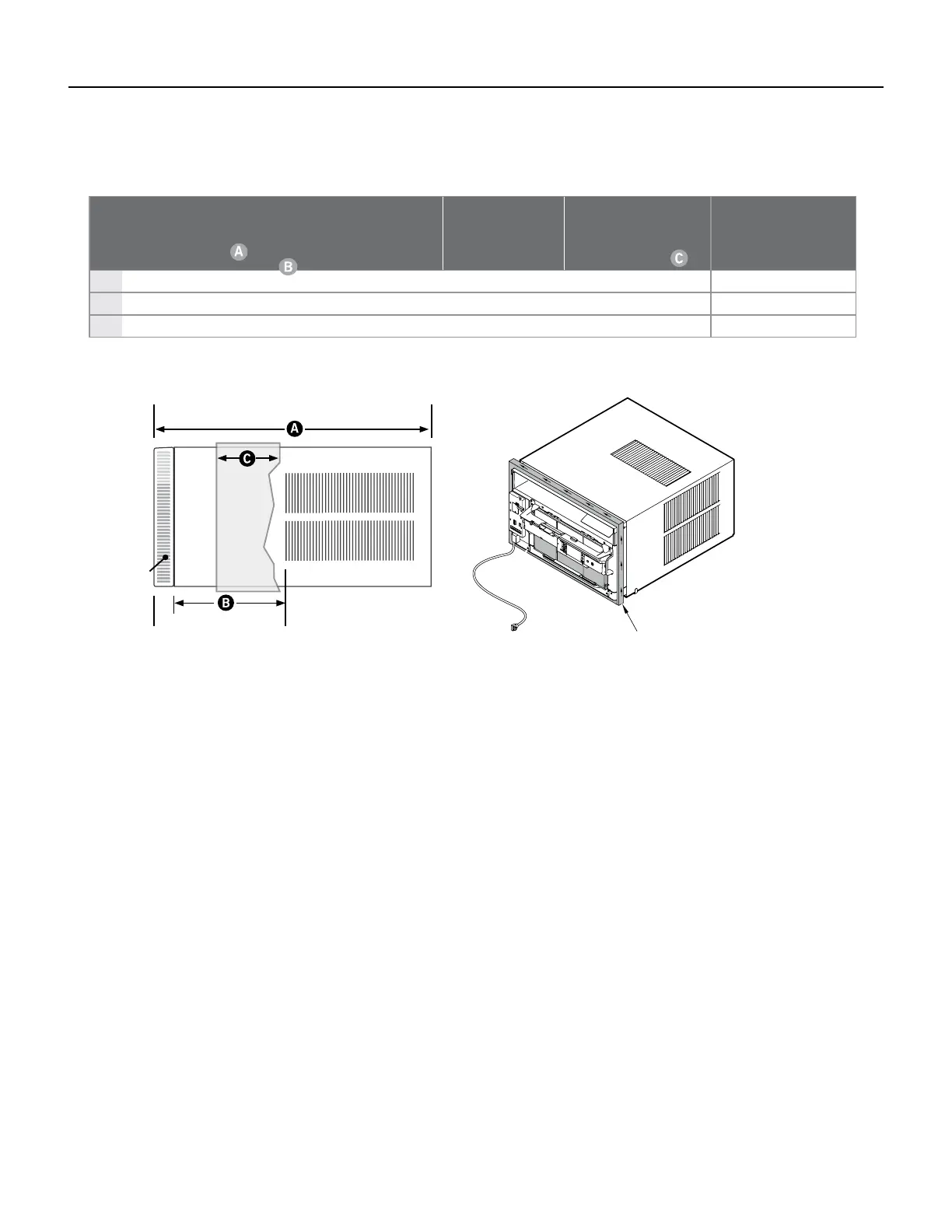
SLEEVE DIMENSIONS DRAWING
NOTE: WHEN INSTALLING THE CHASSIS
SEAL GASKET, BEGIN AT EITHER BOTTOM
CORNER AND GO UP THE SIDE & ACROSS
THE TOP & DOWN THE OPPOSITE SIDE.
Improper installation of chasis seal gasket can cause performance problems and excessive noise or vibration.
If chasis seal damage is worn, damaged, or missing, install new gasket.
For further instructions on the installation of this unit refer to the Installation / Operation Manual (93001015_00)
Installation Clearances
Improper installation of the Air Condtioner can cause poor performance and premature wear of the unit.
Ensure that the KUHL unit is installed with proper clearances as described below.
Ensure no obstructions. or enclosures are within clearances limits to allow for proper airow.
Clearances
Top and Bottom of Unit - One (1) foot
Sides of Unit - One (1) foot
Front of Unit - Three (3) feet
Rear of Unit - Three (3) feet
Figure 203 (Installation Specications)
Figure 204 (Sleeve Dimensions)
Figure 205 (Chasis Gasket)
 Loading...