EasyManua.ls Logo

Friedrich MC24Y3J - Page 56

Friedrich MC24Y3J
90 pages
Print Icon
To Next Page IconTo Next Page
To Previous Page IconTo Previous Page
Loading...
- 56 -
Only for training and service purposes
n AUUW24GD2 [MR24UY3J]
Y^ Y] Y\ Y[ YZ YY YX
w ~ } | u u u
zwtZ
LED02M
LED01M
U
V
W
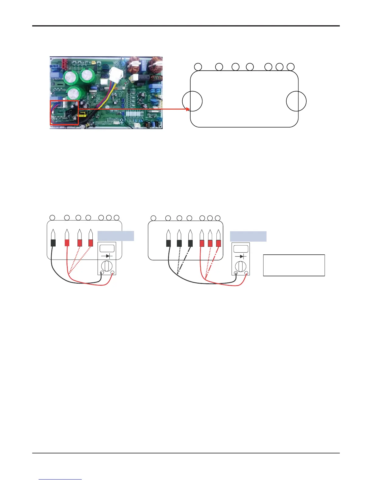
1. Wait until inverter PCB DC voltage is discharged after main power off.
2. Pull out V, V, W COMP connector.
3. Set multi tester to resistance mode.
4.
If the value between P and N terminal of IPM is short(0Ω) or open(hundreds MΩ), PCB needs to be replaced.(IPM damaged)
5. Set the multi tester to diode mode.
6. In case measured value is different from the table, PCB needs to be replaced.(PCB damaged).
27 26 25 24 23 22 21
P W V U Nw Nv Nu P W V U Nw Nv Nu
0.4 ~ 0.6 V
27 26 25 24 23 22 21
0.4 ~ 0.6 V
PFC_IPM check
U, V, W ‘ R S T

Table of Contents

Other manuals for Friedrich MC24Y3J

Related product manuals