A
adamcarterJul 29, 2025
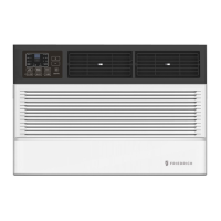
What to do if my Friedrich Air Conditioner is overcharged?
- KKimberly AcostaJul 29, 2025
If your Friedrich Air Conditioner is overcharged, you should check and reduce the refrigerant charge if necessary.
What to do if my Friedrich Air Conditioner is overcharged?
If your Friedrich Air Conditioner is overcharged, you should check and reduce the refrigerant charge if necessary.
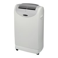
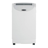
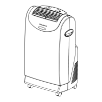
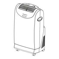
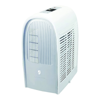
| Type | Portable Air Conditioner |
|---|---|
| Cooling Capacity | 7, 000 BTU |
| Fan Speeds | 3 |
| Voltage | 115V |
| Operating Frequency | 60 Hz |
| Cooling Amps | 6.5 A |
| Cooling Area | 350 sq. ft. |
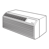
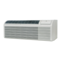
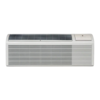
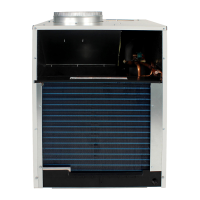
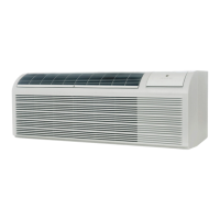
Diagram identifying the key internal and external parts of the PTAC unit.
Explanation of the alphanumeric code used to identify unit series, system, capacity, and options.
Key for decoding the serial number to determine manufacturing date and product line.
Details on receptacle types, fuse/breaker sizes, and recommended wire gauges.
Information on LCDI power cords, including testing procedures and safety warnings.
Allows setting display units (°F/°C) and viewing room/set-point temperature.
Details operation for cooling, heating (including heat pump and resistance), and emergency heat modes.
Explains fan operation modes: fan only, continuous, and cycle control.
Shows room or set-point temperature on LED display for precise control.
Allows direct mode selection (Heat/Cool) without complex power-up sequences.
Unit can be controlled by wall thermostat or optional wireless remote.
Includes self-diagnostics, error logging, temperature limits, freeze protection, and restart delays.
Ensures quick room heating and maintains temperature efficiently using heat pump and electric heat.
Protects compressor from frost and provides backup heat during compressor failure.
Features corrosion resistance, enhanced coil protection, and antimicrobial filters for better air quality.
Guidance on installing and positioning room thermostats for optimal performance.
Details terminal connections for thermostat control of the PTAC unit.
Configuration of temperature limits, fan modes, freeze protection, and emergency heat via dip switches.
Specifies available temperature ranges configurable via dip switches.
Accessing and clearing stored error codes for troubleshooting unit malfunctions.
Entering and using test mode to bypass timers and delays for service diagnostics.
Formula and example for calculating airflow (CFM) based on temperature rise and wattage.
Proper procedures for weighing in refrigerant charge for accurate system operation and longevity.
Symptoms, causes, and checks for units with insufficient refrigerant charge.
Symptoms, causes, and checks for units with excessive refrigerant charge.
Identifies symptoms and diagnostic indicators of a total blockage in the refrigerant circuit.
Identifies symptoms and diagnostic indicators of a partial blockage in the refrigerant circuit.
Details the function and testing procedures for capillary tube metering devices.
Explains the function, operation, and solenoid activation of the 4-way reversing valve.
Procedure to check electrical continuity and grounding of the reversing valve coil.
Tests for proper reversing valve operation and outlines the replacement procedure.
Procedures for testing compressor locked rotor voltage (LRV) and running amperage (LRA).
How to test the compressor's external overload for continuity and proper function.
Tests motor winding resistance (start, run, common) to check for internal defects.
Steps for safely replacing a compressor, including refrigerant recovery and system cleanup.
Procedures for testing capacitor health using analyzers or ohmmeters, and safety precautions.
Correct wiring of motor capacitors and critical safety warnings during handling.
Instructions for cleaning air filters, indoor/outdoor coils, and base pan for optimal performance.
Inspecting blower, fan blades, shroud, surrounding area, sleeve, and drain system for debris.
Periodic inspection of control components and power supply using test instruments.
Flowchart to diagnose cooling system issues based on pressure readings and load conditions.
Flowchart to diagnose heating system issues based on pressure readings and load conditions.
Troubleshooting steps when the system cools instead of heats, checking voltage and selector switch.
Diagnosing and resolving issues with the reversing valve solenoid and proper seating.
Schematic showing electrical connections for cooling-only operation.
Schematic showing electrical connections for cooling with electric heat.
Schematic showing electrical connections for heat pump with electric heat operation.