Do you have a question about the Friedrich SM21N30 and is the answer not in the manual?
Details hazards related to electrical shock, system repairs, and mechanical components.
Information on fire risks from operation and water damage risks from improper servicing.
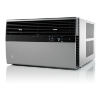
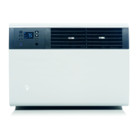
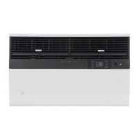
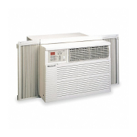
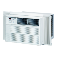
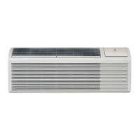
Visual identification of key internal components of the room air conditioner.
Guidance on recording model and serial numbers for future reference.
Explains the structure of model and serial numbers for unit identification.
Specifies electrical circuit ratings, breaker types, and required receptacles for models.
Guidelines for wire size, fuse/breaker selection, grounding, and receptacle compatibility.
Alerts about electrical shock risks and ensuring adequate wiring for the unit.
Step-by-step instructions to test the unit's LCDI power cord safety feature.
Information on remote control, 24-hour timer, and energy management schedule options.
Describes how to turn the unit on and the automatic dimming of the display.
Instructions for selecting system modes and fan operation settings.
How to choose and set timer or pre-programmed schedule functions.
Adjusting display brightness, control panel lock, status icons, and filter alerts.
Instructions for selecting the Timer, Residential Schedule, or Commercial Schedule.
Procedures for setting the unit's clock, day, timer start, and stop times.
Illustrates how the unit operates when the timer is activated or deactivated.
Setup, effectiveness, and operation of remote control buttons.
How to switch temperature display between Fahrenheit and Celsius.
Explains how system parameters are saved and retrieved between modes.
Details compressor/valve operation and the cooling cycle sequence.
Describes heating cycle for heat pump units and the defrost cycle operation.
Details conditions for switching between heat pump and electric heat based on temperature.
Explains compressor lockout feature and fan operation delays during cycles.
Explains fan speed selection for different modes and how fan icons are displayed.
Steps to remove the unit chassis from its sleeve for service.
Instructions for replacing the main electronic control board.
How to adjust louvers for airflow and operate fresh air/exhaust vents.
Procedures for testing fan motors and capacitors with relevant safety warnings.
Explanation of the temperature-sensitive drain pan valve function.
Steps to troubleshoot why the User Interface is not turning on.
Four basic principles and a detailed explanation of the refrigerant flow.
Key points for working with R-410A systems, including pressure and safety.
List of necessary equipment and required capabilities for R-410A system repairs.
Detailed steps for charging the system using the preferred weighed-in method.
How to identify and diagnose systems with insufficient or excess refrigerant charge.
Describes partial and complete restrictions and their diagnostic symptoms.
Procedures for checking capillary tubes and explaining check valve operation.
Explains how the reversing valve controls refrigerant direction in the system.
Steps to test the solenoid coil and check reversing valve shifting.
How to use touch test for diagnosis and procedure for changing the valve.
Procedures for testing compressor voltage, amperage, and overloads.
How to test for compressor grounding and check for faulty compressor valves.
Detailed steps for replacing a compressor, including system preparation and charging.
Steps for flushing and cleaning the system after a compressor burnout.
Instructions for cleaning coils, base pan, blowers, and inspecting electrical components.
How to clean the unit's exterior and inspect surrounding clearances.
Step-by-step instructions for managing the air filter.
Explains how heat pump units function differently, including ice formation and electric heat.
Guidance on troubleshooting, obtaining support, and available accessories.
Procedures for accessing and clearing diagnostic error codes from the unit.
Table detailing error codes, their problems, and control board actions.
Instructions on how to activate test mode to bypass the compressor's 3-minute delay.
Table showing resistance values for thermistors at various temperatures.
Solutions for unit not operating, tripped breakers, or LCDI cord issues.
Troubleshooting tips for insufficient cooling/heating and airflow obstructions.
Explains why units might run longer, including efficiency and sizing.
Troubleshooting tips for compressor not running or fan motor issues.
Solutions for units not cooling properly or evaporator coils freezing.
Troubleshooting tips for units that don't turn off or electronic control board failures.
Explains causes of water spitting and excessive moisture in the room.
Troubleshooting for water leaks originating from outside the unit.
Addresses uneven room temperature in heating and heat pump defrost failures.
Tips for diagnosing and resolving inadequate heating performance.
Cooling cycle diagnosis chart and electrical troubleshooting for heat pumps.
Chart detailing reversing valve malfunctions and their corresponding corrections.
Diagram identifying components on the electronic control board.
Instructions for setting the electronic control voltage to match the unit.
Wiring diagram for various SS, SM, and SL Cool Only models.
Wiring diagram for SL series Cool Only models.
Wiring diagram for SL28 and SL36 Cool Only models.
Wiring diagram for ES and EM Cool with Electric Heat models.
Wiring diagram for the EL36N35-A model.
Wiring diagram for the YS10N10-A heat pump model.
Wiring diagram for YS and YM heat pump models.
Wiring diagram for the YL24N35-A heat pump model.
Instructions for configuring the remote control to operate the air conditioner.
Steps for replacing the User Interface (UI) and its ribbon cable.
Exploded view illustrating the assembly of the standard chassis unit.
List of parts and their numbers for small chassis models.
List of parts and their numbers for medium chassis models.
List of parts and their numbers for large chassis models.
Details warranty coverage for parts and the sealed refrigerant system.
Contact information for authorized Friedrich parts depots.
Contact details for Friedrich Air Conditioning Company for support.
| Refrigerant | R-410A |
|---|---|
| Voltage | 230/208V |
| Fan Speeds | 3 |
| Type | Through-The-Wall |
| Amperage | 10.5 A |
| Power Supply | 230/208V, 60Hz |
| Operating Temperature Range (Cooling) | 60°F - 115°F |