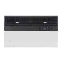
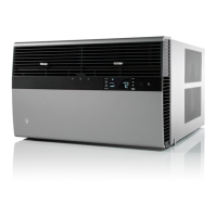
Service Manual
Standard Chassis Models
Room Air Conditioners
115 -Vo lt:
208-230-Volt:
Cool Only
SS08M10, SS10M10, SS12M10, SS14M10
SS12M30, SS15M30, SM18M30, SM21M30
Cool with Electric Heat
208-230-Volt:
Heat Pump with Electric Heat
208-230-Volt:
Heat Pump
115 -Vo lt:
SYSTEM FAN MODE
SCHEDULEFAN SPEED
AUTO
AUTO
AUTO
CONTINUOUS
°F °C
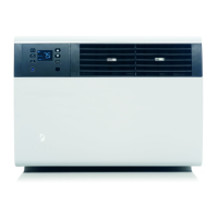
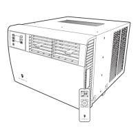
Service Manual
Standard Chassis Models
Room Air Conditioners
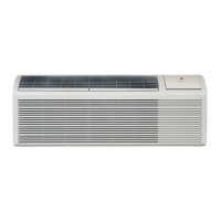
Cool
Electric Heat
Heat Pump
115-Volt:
208-230-Volt:
Cool Only
SS08N10*, SS10N10*, SS12N10*, SS14N10*, SM15N10*
SS12N30*, SS15N30*, SM18N30*, SM21N30*
SM24N30*,SL22N30*, SL24N30*, SL28N30*, SL36N30*
Cool with Electric Heat
208-230-Volt: ES12N33*, ES15N33*, EM18N34*, EM24N34*, EL36N35*
Heat Pump with Electric Heat
208-230-Volt: YS12N33*, YM18N34*, YL24N35*
Heat Pump
115-Volt: YS10N10*
Kuhl-Serv/PartsMan (9-12) *Last character may vary
2012 Service/Parts Manual
FAN SPEED
SCHEDULE
SYSTEM
FAN MODE
POWER
F
AUTO FAN
AUTO
CONTINUOUS
C