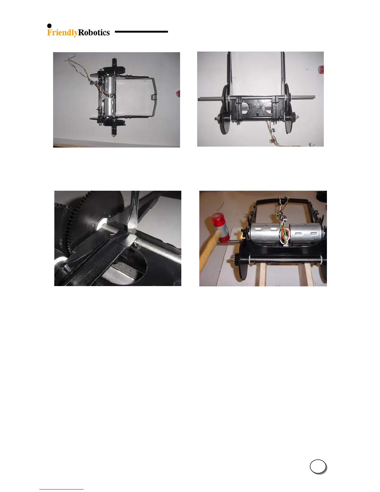
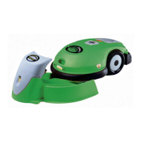
Figure 4.2.6.4.1 Figure 4.2.6.4.2
A complete gearbox out of the Robomow A gearbox without the spline and slider
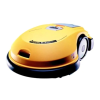
Figure 4.2.6.4.3 Figure 4.2.6.4.4
Removing the shaft clips Extracting the long shaft out of a gearbox on
supporting blocks
G. Turn the gearbox so the drive motors will face towards the table. Use a plastic hammer to hit
on each side of the short shaft, as illustrated in Figure 4.2.6.3.5.
H. Discard of both shafts. Turn the gearbox again and place it on the wooden supports so the
drive motors will face up. From the new shafts kit, take the short shaft and place it near the
gear frame groove. The white bushings will sit against the frame, as illustrated in Figure
4.2.6.3.6.
I. Tap on both sides of the shaft with a plastic hammer until both bushings will “pass” the gear
frame corner, as illustrated in Figure 4.2.6.3.7.
J. Hit both sides of the shaft with a plastic hammer until it will fully and firmly sit inside the gear
frame groove, as illustrated in Figure 4.2.6.3.8.
4
28