4.3 Power Pack Procedures
The Power Pack is not designed to be opened for service or repair as it does not contain either
moving parts or parts that are expected to fail. However, procedures are included to allow access
if necessary.
4.3.1 Power Pack opening and cable layout
Required tools: Flat screwdriver Procedure duration: 10 minutes
A. Remove the Power Pack from the Robomow.
B. Identify the two notches on the side-wall of the
power pack.
C. Identify the latch that can be seen through these
notches just behind the side-wall.
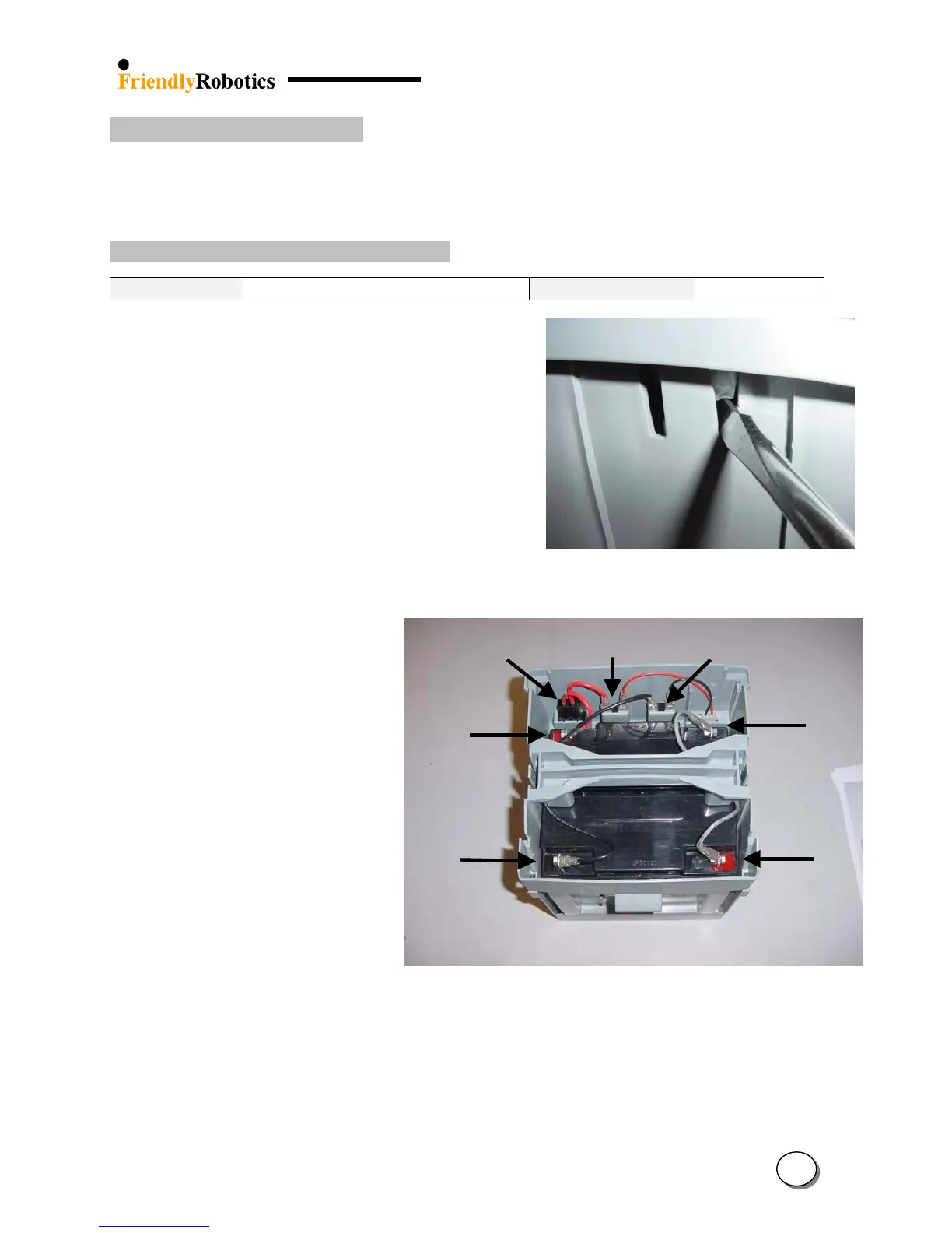
D. Insert a flat screwdriver through the notch and
reach behind the latch.
E. With one hand pull up on the cover just above the
screwdriver while simultaneously using the
screwdriver to pull the latch, as illustrated in Figure
4.3.1.1.
Figure 4.3.1.1
Opening the Power Pack cover
F. Repeat step ‘D’ and ‘E’ for the other sides of the
power pack.
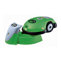
Power
Pack fuse
(+)
erminal
(-)
Terminal
(+)
(+)
(-)
(-)
Figure 4.3.1.2
The inside of a
G. The inside arrangement and
cable layout of the power pack
is outlined in Figure 4.3.1.2
H. In order to close the power pack cover, place the cover over the case in its proper position and
hit the cover, straight on the latch, to force them down into their notches. Verify the cover fits
tightly in place.
I. Place the power pack into a Robomow, plug in a charger and verify there is indication of
charging process on the Manual Controller display.
4
47