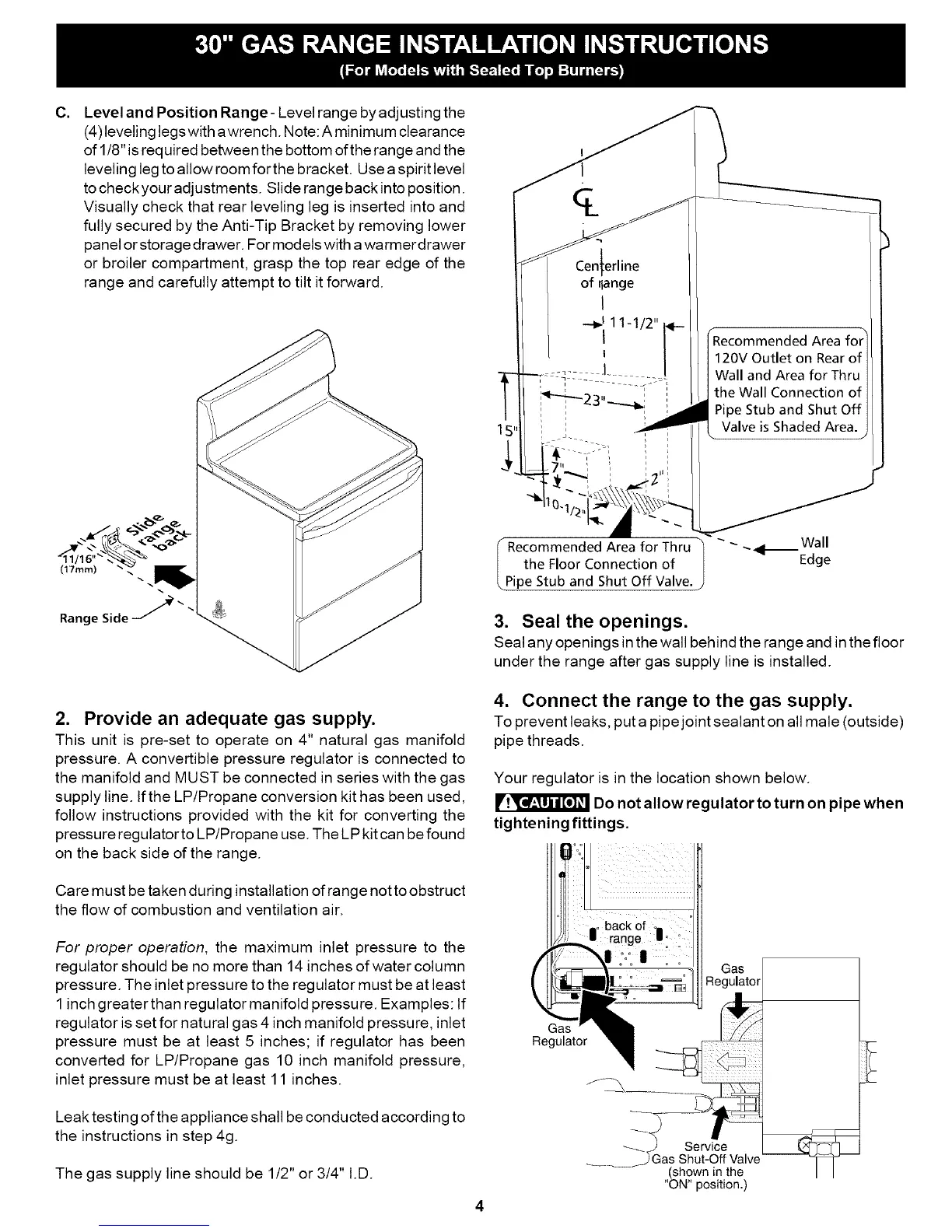
C.
Level and Position Range- Level range by adjusting the
(4) leveling legs with awrench. Note: A minimum clearance
of 1/8" is required between the bottom of the range and the
leveling leg to allow room for the bracket. Use a spirit level
tocheckyour adjustments. Slide range back into position.
Visually check that rear leveling leg is inserted into and
fully secured by the Anti-Tip Bracket by removing lower
panel or storage drawer. For models with awarmer drawer
or broiler compartment, grasp the top rear edge of the
range and carefully attempt to tilt it forward.
(17ram)
Range Side /
2. Provide an adequate gas supply.
This unit is pre-set to operate on 4" natural gas manifold
pressure. A convertible pressure regulator is connected to
the manifold and MUST be connected in series with the gas
supply line. If the LP/Propane conversion kit has been used,
follow instructions provided with the kit for converting the
pressure regulator to LP/Propane use. The LPkit can be found
on the back side of the range.
Care must be taken during installation of range not to obstruct
the flow of combustion and ventilation air.
For proper operation, the maximum inlet pressure to the
regulator should be no more than 14 inches of water column
pressure. The inlet pressure to the regulator must be at least
1inch greater than regulator manifold pressure. Examples: If
regulator is set for natural gas 4 inch manifold pressure, inlet
pressure must be at least 5 inches; if regulator has been
converted for LP/Propane gas 10 inch manifold pressure,
inlet pressure must be at least 11 inches.
Leak testing of the appliance shall be conducted according to
the instructions in step 4g.
The gas supply line should be 1/2" or 3/4" I.D.
I
of _ange ,,
Recommended Area for
120V Outlet on Rearof
Wall and Area for Thru
the Wall Connection of
Pipe Stub and Shut Off
Valveis ShadedArea.
Area for Thru "_ " "_4t-- wall
the Floor Connection of l Edge
Pipe Stub and Shut Off Valve.
3. Seal the openings.
Seal any openings in the wall behind the range and in the floor
under the range after gas supply line is installed.
4. Connect the range to the gas supply.
To prevent leaks, put a pipe joint sealant on all male (outside)
pipe threads.
Your regulator is in the location shown below.
Do not allow regulator to turn on pipe when
tightening fittings,
4
(shown in the
"ON" position.)