7
Vent system must terminate to the outdoors.
Do not terminate the vent system into an attic or other
enclosed area.
Do not use a 4” (10.2 cm) laundry-type wall cap.
Use a 3¼´[´[FPUHFWDQJXODUPHWDO
vent. Rigid metal vent is recommended. Plastic or
metal foil vent is not recommended.
The length of vent system and number of elbows
VKRXOGEHNHSWWRDPLQLPXPWRSURYLGHHI¿FLHQW
performance.
)RUWKHPRVWHI¿FLHQWDQGTXLHWRSHUDWLRQ
Use no more than three 90° elbows.
Make sure there is a minimum of 24” (61 cm) of straight
vent between the elbows if more than 1 elbow is used.
Do not install 2 elbows together.
Use clamps or duct tape to seal all joints in the
vent system.
7KHYHQWV\VWHPDWH[LWPXVWKDYHDFROGDLUGDPSHU
8VHFDXONLQJWRVHDOH[WHULRUZDOORUURRIRSHQLQJ
around the cap.
Best performances are reached with straight piping,
without elbows and using smooth pipe.
0D[LPXPUHFRPHQGHGYHQWV\VWHPOHQJWKIWP
Cold Weather Installations
An additional back draft damper should be installed to
PLQLPL]HEDFNZDUGFROGDLUÀRZDQGDWKHUPDOEUHDN
should be installed to minimize conduction of outside tem-
peratures as part of the vent system. The damper should
be on the cold air side of the thermal break.
The break should be as close as possible to where the
vent system enters the heated portion of the house.
Makeup Air
Local building codes may require the use of makeup air
systems when using ventilation systems greater than
VSHFL¿HG&)0RIDLUPRYHPHQW7KHVSHFL¿HG&)0YDULHV
from locale to locale. Consult your HVAC professional for
VSHFL¿FUHTXLUHPHQWVLQ\RXUDUHD
Venting Methods
Vent system can terminate either through the roof or wall.
Use 3¼´[´[FPUHFWDQJXODUZLWKDPD[LPXP
vent length of 35 ft (10.7 m) or 7” (17.8 cm) round vent with
DPD[LPXPOHQJWKRIIWPIRUYHQWV\VWHP
NOTE
)OH[LEOHYHQWLVQRWUHFRPPHQGHG)OH[LEOHYHQW
creates both back pressure and air turbulence
that greatly reduce performance.
•
•
•
•
•
•
•
•
•
•
•
•
•
Calculating Vent System Length
To calculate the length of the system you need, add the
equivalent feet (meters) for each vent piece used in the
system.
7” (17.8 cm) Round Vent System
Vent Piece
90° elbow 5.0 ft
(1.5 m)
7” (17.8 cm) wall cap 0.0 ft
(0.0 m)
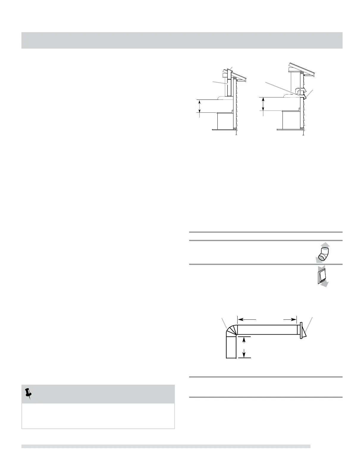
([DPSOH9HQW6\VWHP
A
B
C
A
B
C
A. 3¼´[´[FP
rectangular vent through the
roof. (purchased separately)
B. Roof cap with damper
(purchased separately)
C. 24” (61.0 cm) min. to 30”
(76.2cm) above the cooking
surface
A. 3¼´[´[FP
rectangular vent through the
wall or out the top
(purchased separately)
B. Wall cap with damper
(purchased separately)
C. 24” (61.0 cm) min. to 30”
(76.2cm) above the cooking
surface
Roof Venting Wall Venting
0D[LPXP5HFRPPHQGHG/HQJWK IWP
HOERZ IWP
IWPVWUDLJKW IWP
ZDOOFDS IWP
/HQJWKRI´FPV\VWHP IWP
2 ft (0.6 m)
7” (17.8 cm) round
90° elbow
6 ft (1.8 m)
Wall Cap
VENTING REQUIREMENTS