Do you have a question about the Frigidaire PLMV178HC and is the answer not in the manual?
Observe precautions to avoid possible exposure to excessive microwave energy during servicing.
Adhere to manual procedures, check grounds, use correct parts, and handle ESD sensitive devices.
Warnings about high voltage presence, capacitor charging, and proper discharge procedures.
Detailed specifications including timer, power source, consumption, output, magnetron, and dimensions.
Diagram and description of the microwave oven's control panel buttons and functions.
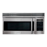
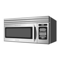
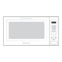
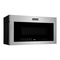
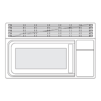
Illustrations and labels identifying key external features and internal components of the oven.
Visual list of items included with the microwave oven, such as glass tray, filters, and manuals.
Details on the bracket assembly, mounting to wall/cabinet, and weight support capacity.
Information on the vent blower, cooktop lights, and oven light replacement.
Instructions for installing, cleaning, and removing reusable grease and charcoal filters.
Explanation of the automatic fan feature and procedures for removing the top grille.
Step-by-step guide for safely removing the microwave oven from its wall mounting.
Procedure for replacing the high voltage transformer, including safety steps.
Steps for safely removing and replacing the magnetron, including gasket notes.
Detailed steps for removing specific door components ('C' and 'E') and key door spring.
Instructions for reassembling the door and performing a microwave leakage test.
Procedure for replacing the fuse, including checks for related switches and components.
Steps to disconnect, remove, and reconnect the turntable drive motor.
Instructions for removing the stirrer motor, including grille and bracket duct disassembly.
Procedure for removing the stirrer cover and the stirrer itself from the waveguide.
Steps to remove the control box and the Printed Circuit Board (PCB) assembly.
Guidelines for removing and installing the window display and membrane keypad.
Procedure for servicing the humidity sensor and performing a quick diagnostic test.
Procedure for checking the continuity of the high voltage transformer terminals.
How to check magnetron filament and case for continuity and shorts.
Methods for testing the high voltage capacitor's continuity and terminal resistance.
Instructions for measuring the forward and reverse resistance of the high voltage diode.
How to test main and power control relays for continuity using a water load.
Procedure for aligning and adjusting primary, interlock, and door sensing switches.
Steps to test the run capacitor for the vent blower motor.
Procedure for testing blower motor windings for continuity.
Instructions for removing the vent blower assembly from the oven installation.
Location and characteristics of the oven thermal cutout used as a flame sensor.
Description of the hood thermal cutout's role and procedure for its removal.
Details on the bottom thermal cutout's function during a fire and its removal process.
Explanation of the magnetron thermal cutout's purpose and how to remove it.
Method for measuring magnetron output power using a water temperature rise test.
Detailed steps for measuring microwave leakage and acceptable limits.
Areas to check for microwave leakage, including magnetron opening and wave guide.
Important notes and warnings for accurate microwave leakage measurements.
Guidelines for recording leakage measurements and notifying the service center.
Essential precautions before troubleshooting, including grounding and HV capacitor discharge.
Troubleshooting for oven being dead or displaying no operation, listing potential causes.
Diagnosing issues when the fuse is blown, including related switch checks.
Causes and corrections for the oven not accepting key input or program.
Addressing the symptom of timer counting down but no microwave oscillation (no heat).
Troubleshooting for oven lamp and fan motor turning on, but no program start.
Diagnosing low microwave output, fan motor operation, and buzzing noises.
Troubleshooting turntable motor, sparks, uneven cooking, and noise.
Explanation of error codes related to key input, sensor unplugging, or shorts.
An exploded view diagram illustrating the assembly of microwave oven components.
Detailed list of all parts with their corresponding numbers and quantities for the PLMV178HC model.
Wiring diagram illustrating the electrical connections and components of the microwave oven.
| Capacity | 1.7 cu. ft. |
|---|---|
| Power | 1000 Watts |
| Installation Type | Over-the-Range |
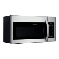
| Color | Stainless Steel |
| Child Safety Lock | Yes |
| Voltage | 120V |
| Type | Over-the-Range |
| Cooking Modes | Reheat, Defrost, Popcorn |
| Control Type | Electronic Touch |