19
4
0
0
S
E
R
I
E
S
W
a
t
e
r
C
Y
C
L
E
R
M
e
t
e
r
e
d
P
o
o
l
P
u
r
i
f
i
e
r
4
0
0
S
E
R
I
E
S
W
a
t
e
r
C
Y
C
L
E
R
M
e
t
e
r
e
d
P
o
o
l
P
u
r
i
f
i
e
r
4
0
0
S
E
R
I
E
S
W
a
t
e
r
C
Y
C
L
E
R
M
e
t
e
r
e
d
P
o
o
l
P
u
r
i
f
i
e
r
W
a
t
e
r
C
Y
C
L
E
R
M
e
t
e
r
e
d
P
o
o
l
P
u
r
i
f
i
e
r
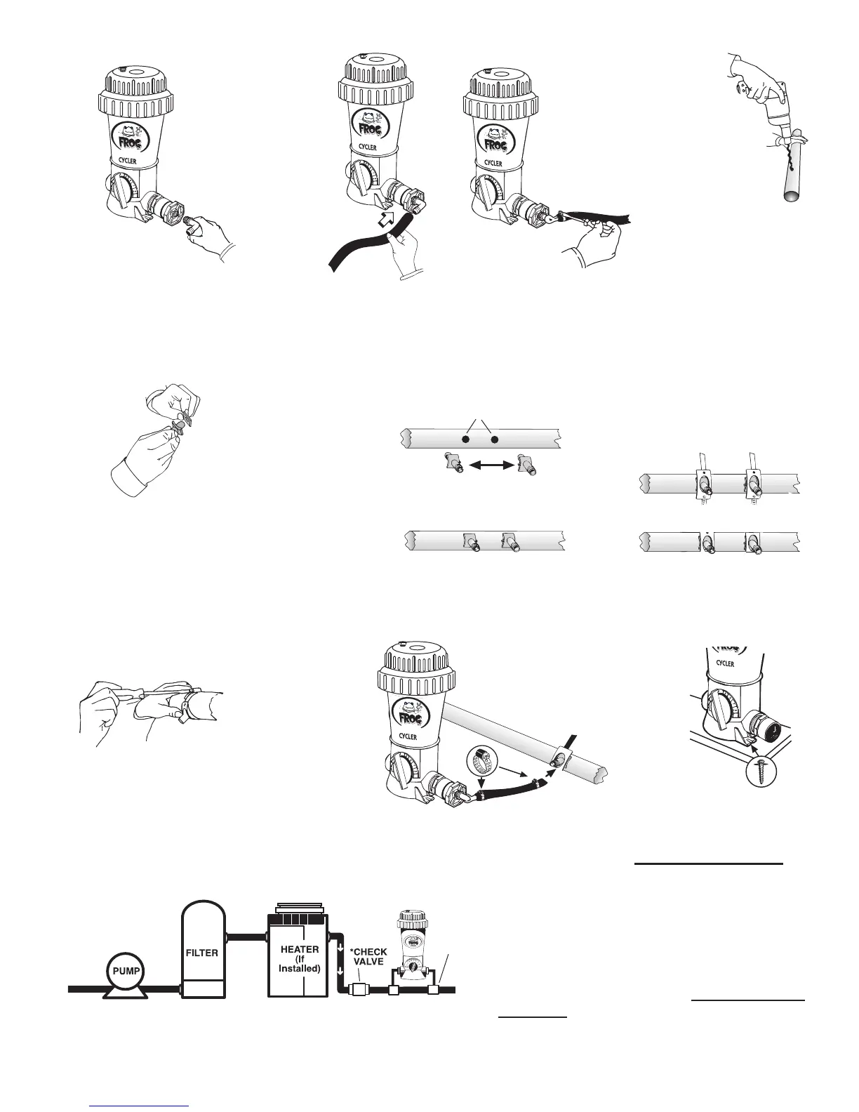
2” – 36” apart on straight pipe
SCOOPS 2”– 36”
APART ON STRAIGHT
PIPE
Screw elbow into reducer
bushings on both sides.
Attach a gasket to
each scoop.
Tighten scoop clamps with a
screwdriver.
Cut tubing
to size for
each POOL
FROG
®
Cycler
connection
and attach one
to each elbow
with clamps.
Place scoops inside
holes so the inlet
scoop faces the water
ow and the outlet
scoop faces away
from the water ow.
Scoop arrows should
be facing each other
when correct.
Attach each hose to
venturi scoop male
nipple with a small
clamp and tighten
with screwdriver.
Tighten clamps
with screwdriver.
When pipe is
totally dry, drill two
19/32” or 5/8”
holes, between
2” - 36” apart, on
the return line. Be
careful not to go
through other side
of pipe.
Arrows on scoops must
face each other.
For better stability, POOL
FROG
®
Cycler may be mounted
on a treated wood base using
Phillips pan head screws.
One in front and one in back.
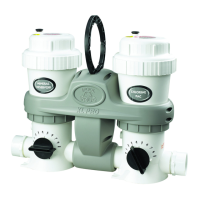
When using a POOL FROG
®
Bac Pac, isolating the
POOL FROG
®
Cycler by installing a corrosion resistant
check valve is recommended, especially if a heater is
installed.
6.
7.
8.
9.
10.
11. 12.
13.
14. 15.
16.
Attach scoop clamps over the
scoops and around the pipe.