Rear view of DPS 2500
(1) Blanking cap
(2) Malfunction indicator
glows until the interface has been initialised by the external control, and if a mal-
function has occurred during operation. The error messages displayed here are
described in the section headed “Troubleshooting”.
(3) Robot-interface indicator
glows when the power source is “On”, if e.g. a robot interface or field-bus coupler
is connected up to the LocalNet and there is a datalink to the interface.
(4) Power source “ON” indicator
glows as long as the power source is connected up to the mains supply and the
mains switch is in the “I” position
(5) “Operating instructions” symbol
Observe all the safety, operating, care and maintenance instructions in the “Ope-
rating instructions” manual!
(6) Mains switch
for switching the power source on and off
(7) (+) current socket with bayonet latch
for connecting the current cable
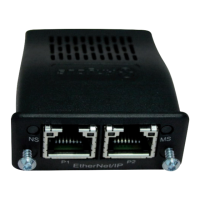
(8) Interface
for connecting the power source to the control system. Please see the interface
instruction manual for details of the designations of the various connections
(9) (-) current socket with bayonet latch
for connecting the current cable
40