81
g
Data Communication and Solar Net
Solar Net and
Data Interface
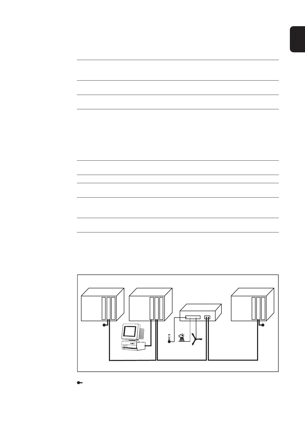
Example Logging and archiving inverter and sensor data using a Fronius Datalogger and Fronius
Sensor Box:
Illustration explanation: Data network with 3 Fronius IG Plus units and one Fronius Sensor
Box:
Fronius developed Solar Net to make these add-on system components flexible and ca-
pable of being used in a wide variety of different applications. Solar Net is a data network
which enables several inverters to be linked with the system upgrades.
Solar Net is a bus system. A single cable is all that is required for one or more inverters
to communicate with all system upgrade components.
The core of the Solar Net is the Fronius Datalogger. It coordinates the data traffic and
makes sure that even large volumes of data are distributed quickly and reliably.
The 'Fronius COM Card' option is required to integrate an inverter into Solar Net.
Important Every inverter that is to be monitored using a Datalogger requires a 'Fronius
COM Card.' In this case, the ‘Fronius Com Card’ serves as a link between the internal
network of the inverter and the Solar Net interface of the Fronius Datalogger.
Important Each inverter can only have one 'Fronius Com Card.' A network may only con-
tain one Fronius Datalogger.
The first inverter with a 'Fronius COM card' can be up to 1000 m (3280 ft) away from the
last inverter with a 'Fronius COM card.'
Different system upgrades are detected automatically by Solar Net.
In order to distinguish between several identical system upgrades, each one must be as-
signed a unique number.
In order to uniquely identify each inverter in Solar Net, each inverter must also be as-
signed an individual number. You can assign individual numbers as per 'The Setup Menu'
section in this manual.
More detailed information on the individual system upgrades can be found in the relevant
operating instructions or on the Internet at http:\\www.fronius.com.
= Terminating plug
12 3
Fronius
IG Plus
Fronius
IG Plus
Fronius
IG Plus
Com Card
Datalogger C.
IN
OUT
Com Card
Com Card
IN
OUT
RS 232
IN
OUT
Sensor Box
IN OUT
°C
W/m²
m/s
PC