Do you have a question about the Fronius Symo 17.5-3-M and is the answer not in the manual?
Explains the meaning of DANGER, WARNING, CAUTION, NOTE, and IMPORTANT symbols.
General safety rules and precautions for device operation.
Requirements and responsibilities for service personnel.
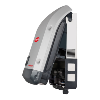
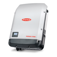
Overview of the inverter's design and internal components.
Outlines the intended purpose and correct usage of the inverter.
Explains the warning notices and safety symbols found on the inverter.
Guidelines for selecting appropriate string fuses for solar modules.
Identifies controls, connections, and displays on the Datamanager.
Steps for initial setup and connecting the Datamanager.
Description of the inverter display and monitoring/status LEDs.
Details on the function and operation of the navigation keys.
Information on initial settings and software updates.
How to activate/deactivate standby mode and resume operation.
Displays the status of the most recent fault and grid faults.
Procedure for activating and deactivating the inverter's key lock.
Using the USB drive for logging data from the inverter.
Technical specifications for Fronius Symo 3.0-3-S, 3.7-3-S, and 4.5-3-S.
Technical specifications for Fronius Symo 3.0-3-M, 3.7-3-M, and 4.5-3-M.
Technical specifications for Fronius Symo 5.0-3-M, 6.0-3-M, and 7.0-3-M.
Technical specifications for Fronius Symo 8.2-3-M.
Technical specifications for Fronius Symo 10.0-3-M and 12.5-3-M.
Technical specifications for Fronius Symo 15.0-3-M, 17.5-3-M, and 20.0-3-M.
Technical specifications for Fronius Eco 25.0-3-S and 27.0-3-S.
| AC Nominal Power | 17.5 kW |
|---|---|
| Max. Input Voltage | 1000 V |
| MPPT Voltage Range | 200 - 800 V |
| Number of MPP Trackers | 2 |
| Efficiency | 98.1% |
| Frequency | 50 / 60 Hz |
| Protection Class | IP65 |
| Operating Temperature Range | -25°C to +60°C |
| Max. Apparent AC Power | 17, 500 VA |
| AC Voltage Range | 3 x 230 / 400 V |
| Cooling Method | Forced air cooling |






 Loading...