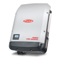
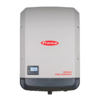
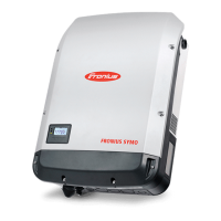
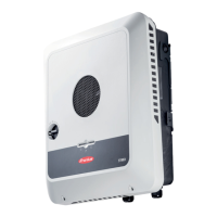
Do you have a question about the Fronius Symo 10.0-3-M and is the answer not in the manual?
Defines DANGER, WARNING, CAUTION, NOTE, and IMPORTANT symbols.
General safety precautions, device compliance, notices, and temperature.
Specifies conditions for operation or storage outside stipulated areas.
Information for qualified personnel, cable requirements, and maintenance.
Discusses sound power level, cooling, and EMC impact.
Compliance with disposal directives and user data protection responsibilities.
States copyright of instructions and reserves the right to make changes.
Describes the inverter's components and basic operational principles.
Defines intended use, prohibited actions, and device warning notices.
Electrical hazards, DRM control, dummy devices, and string fuses.
Provides criteria for selecting suitable fuses for solar module strings.
Explains the Fronius Solar Net system and data interface.
Details the physical data communication connections on the inverter.
Explains the meaning of the 'Solar Net' LED status.
Illustrates data recording and explains the multifunction current interface.
Explains wiring for surge protection and S0 meter connections.
Details the physical controls, connections, and display elements.
Explains WLAN, Solar.web, Supply, Connection LEDs, and interfaces.
Details power supply, antenna, Modbus, and Master/Slave switch functions.
Explains access limitations and procedures when DC voltage is low.
Guides through the initial setup and connection process.
Steps for installing and accessing via App or web browser.
Provides a link for additional details on Datamanager 2.0 and start-up.
Describes the main display and various status LEDs.
Details the functions of the navigation and selection keys.
Shows display layouts in normal and setup modes.
Controls display backlighting and how to open the main menu.
Lists and briefly describes NOW, LOG, GRAPH, SETUP, and INFO menus.
Details the real-time values shown in the 'NOW' menu.
Details the recorded data shown in the 'LOG' menu.
Explains initial setup automation and notes on software update discrepancies.
Guides on how to enter, scroll, and exit the SETUP menu.
General procedure for setting values and an example for setting the time.
Detailed steps for setting the current time.
Explains Standby mode and DATCOM configuration for data communications.
Details USB usage for logging/updates and setting the logging interval.
Covers relay functions, tests, and Energy Manager activation.
Setting time, date, display format, language, and night mode.
Adjusting display contrast, illumination, and energy yield settings.
Setting currency, feed-in tariff, and testing the fan.
Setting the remuneration rate and testing the fan's operation.
Displays PV insulation, DC voltage, power reduction, and fault status.
Shows grid faults and general device configuration details.
Displays grid monitoring data and voltage/frequency limits.
Covers power limits, voltage derating, and fault ride through configuration.
Displays software and hardware version information.
Explains the purpose and access restrictions of the key lock function.
Describes USB logging and lists recommended drive types.
Explains software updates via USB and safe removal procedures.
Steps to access and navigate the Basic menu with items listed.
Covers DC modes, USB log, input signals, SMS/relay, insulation, reset, and DC SPD.
Explains status codes, display failure, and Class 1 grid errors.
Covers status codes that cause brief interruptions during grid feeding.
Details status codes requiring intervention by a service technician.
Continues listing class 4 status codes and their remedies.
Covers status codes causing restrictions but not interrupting grid feeding.
Details status codes requiring intervention by a service engineer.
Covers status codes related to control system, configuration, and data recording.
Information on internal processor program status codes.
Contact information for support and maintenance in dusty conditions.
Provides detailed specifications for Fronius Symo 3.0-4.5 kW models.
Provides detailed specifications for Fronius Symo 3.0-4.5 M kW models.
Provides detailed specifications for Fronius Symo 5.0-7.0 M kW models.
Provides detailed specifications for the Fronius Symo 8.2-3-M model.
Provides detailed specifications for Fronius Symo 10.0-12.5 kW models.
Provides detailed specifications for Fronius Symo 15.0-20.0 kW models.
Provides detailed specifications for Fronius Eco 25.0-27.0 kW models.
Clarifies footnotes, CE mark, and operational guidelines.
| Max. output current | 16.7 A |
|---|---|
| Max. input voltage | 1000 V |
| MPP voltage range | 200 - 800 V |
| Number of MPP trackers | 2 |
| Protection class | IP 65 |
| AC voltage range | 150 - 280 V |
| Frequency | 50 / 60 Hz |
| THD | < 3 % |
| AC Nominal Power | 10000 W |
| MPPT Voltage Range | 200 - 800 V |
| AC Frequency | 50 / 60 Hz |
| AC nominal output | 10000 W |
| Max. apparent AC power | 10000 VA |
| DC input voltage range | 200-1000 V |
| Operating Temperature | -25°C to +60°C |
| Dimensions (W x H x D) | 725 x 510 x 225 mm |
| AC nominal voltage | 3 x 230 / 400 V |


 Loading...