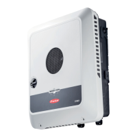
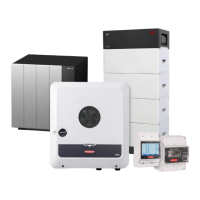
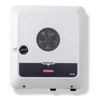
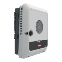
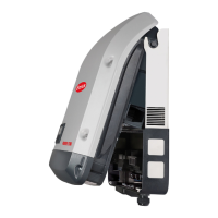
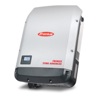
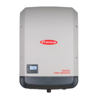
Do you have a question about the Fronius Symo GEN24 10.0 and is the answer not in the manual?
Outlines general safety standards, risks of misuse, and requirements for personnel.
Details the qualifications and responsibilities of personnel involved in servicing the device.
Explains the connection to earth for shock protection and grounding conductor requirements.
Explains the inverter's function in converting DC to AC and its use in grid-connected PV systems.
Defines the inverter's intended purpose and what constitutes improper use, voiding warranty.
Illustrates energy flow for self-consumption using a battery for excess energy storage.
Illustrates energy flow during backup power mode, highlighting load supply and battery/grid feed-in.
Illustrates operation with battery, Ohmpilot, and backup power, noting Ohmpilot limitations.
Shows a hybrid system with multiple inverters and backup power functionality.
Identifies various push-in terminals and cable glands in the connection area.
Explains Modbus terminals, WSD switch, and their functions.
Details voltage output, current limits, appliance behavior, and interruption aspects of the PV Point.
Lists essential requirements like inverter support, battery installation, correct cabling, and meter configuration.
Describes the process of switching from grid-connected to backup power mode upon grid failure.
Explains how the system returns to grid-connected operation when the public grid is restored.
States that warning notices are affixed to the inverter and must not be removed.
Provides criteria for selecting an inverter location, including clearances, temperature, and humidity.
Explains how to use integrated grips and secure the inverter into the bracket until it clicks.
Discusses national regulations for residual current circuit breakers and recommended fuse ratings.
Details safety precautions regarding incorrect operation, grid voltage, and contaminated terminals.
Outlines the procedure for connecting the inverter to the public grid, including neutral conductor requirements.
Details the step-by-step process for turning off breakers, opening covers, and connecting AC cables.
Emphasizes safety warnings related to PV string connections, including electric shock and earthing requirements.
Explains the availability of two PV inputs and configuration options for PV generators.
Provides safety warnings for connecting batteries, including electric shock and altitude risks.
Details the importance of switching off the battery before installation and considering DC cable length.
Emphasizes national laws, grid operator specs, and safety for PV Point installation.
Provides safety warnings and recommendations for coordinating with grid operators and avoiding UPS operation.
Explains the importance of testing backup power mode after installation and refers to a checklist.
Describes the initial setup process, including configuration settings and handling interruptions.
Guides the user through the installation process using the mobile app.
Details the procedure for installation via WLAN and Ethernet using a web browser.
Explains how to log in to the inverter's user interface using username and password.
Outlines options for backup power mode (Off, PV Point, Full Backup) and important considerations.
Details backup power settings like nominal voltage, undervoltage/overvoltage protection, restart attempts, and external frequency check.
Details setting modes for optimization and target values at the feed-in point.
Discusses energy company stipulations for feed-in limitations and how to set custom limits.
Details options for feed-in limitation, including 'Off', 'Limit for entire system', and 'Limit per phase' with examples.
Describes the autotest for checking Italian grid code requirements, including voltage and frequency limits.
Details the safety precautions and steps required before de-energizing the inverter for installation.
Covers safety warnings for SPD installation and the initial steps of disconnecting power and module strings.
Describes the initial steps for commissioning, including connecting PV strings and switching on the battery.
Emphasizes safety warnings regarding grid voltage, DC voltage, and residual voltage during maintenance.
Provides specific remedies for the WSD Open error, including installing bypass or trigger devices and setting the WSD switch.
Lists DC input specifications such as MPP voltage range, connected load, processable power, and input current.
Details AC input/output specifications including rated power, mains voltage, frequency, and harmonic distortion.
Covers general data, protection class, and communication interfaces.
Lists DC input specifications for the 8.0/8.0 Plus models.
Details AC input/output specifications for the 8.0/8.0 Plus models.
Covers general data, protection devices, and communication interfaces for the 8.0/8.0 Plus models.
Lists DC input specifications for the 10.0/10.0 Plus models.
Details DC input data related to batteries for the 10.0/10.0 Plus models.
Details AC input/output specifications for the 10.0/10.0 Plus models.
Covers general data, protection devices, and communication interfaces for the 10.0/10.0 Plus models.
Provides technical specifications for the DC SPD, including general, mechanical, and test standard data.
Provides the circuit diagram for the PV Point backup power variant.
Shows the circuit diagram for connecting Fronius GEN24 with a BYD Battery-Box Premium HV.
Illustrates the circuit diagram for connecting two BYD Battery-Box Premium HV units in parallel with Fronius GEN24.
Shows the circuit diagram for connecting three BYD Battery-Box Premium HV units in parallel with Fronius GEN24.
Provides the circuit diagram for automatic backup power switching with 3-pin double separation in Austria.
Shows the circuit diagram for automatic backup power switching with 3-pin single separation in Australia.
Illustrates the circuit diagram for backup power with 3-pin double separation and external grid protection in Italy.
Provides the circuit diagram for automatic backup power switching with 4-pin double separation in Germany.
Shows the circuit diagram for backup power switching with 4-pin single separation in France and Spain.
Illustrates the circuit diagram for backup power with 4-pin double separation and external grid protection in Italy.
| Model | Fronius Symo GEN24 10.0 |
|---|---|
| Category | Inverter |
| AC nominal output | 10.0 kW |
| AC grid frequency | 50 Hz / 60 Hz |
| THD | < 3 % |
| Number of MPP trackers | 2 |
| Protection class | IP66 |
| AC Nominal Voltage | 230 V / 400 V |
| Operating Temperature Range | -25°C to +60°C |
| Max. apparent AC power | 10, 000 VA |
| AC nominal voltage range | 230 V |
| DC connection | 4x DC+ and 4x DC- screw terminals |
| Maximum AC Power | 10000 VA |
| Maximum DC Power | 15 kW |
| AC Voltage Range | 180 - 280 V |
| Cooling | Active cooling |
| Warranty | 5 years |

