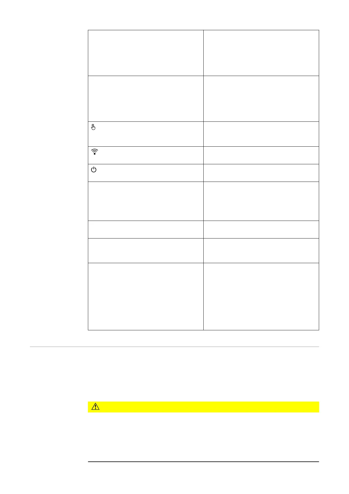
Modbus 0 (MB0) switch Switches the terminating resistor for
modbus 0 (MB0) on/off.
Position 1: Terminating resistor on
(factory setting)
Position 0: Terminating resistor off
Modbus 1 (MB1) switch Switches the terminating resistor for
modbus 1 (MB1) on/off.
Position 1: Terminating resistor on
(factory setting)
Position 0: Terminating resistor off
Optical sensor
To operate the inverter. See chapter
Button functions and LED status in-
dicator on page 95.
Communication LED
Indicates the inverter connection
status.
Operating status LED
Indicates the inverter operating
status.
LAN 1 Ethernet connection for data commu-
nication (e.g. WLAN router, home net-
work or for commissioning with a
laptop see chapter Installation using
the web browser on page 97).
LAN 2 Reserved for future functions. Only
use LAN 1 to avoid malfunctions.
WSD terminal Push-in terminal for the WSD installa-
tion. See chapter "WSD (wired shut-
down)" on page 30.
IOs terminal Push-in terminal for digital inputs/
outputs. See chapter Permitted
cables for the data communication
area on page 61.
The designations (RG0, CL0, 1/5, 2/6,
3/7, 4/8) on the terminal refer to the
Demand Response Mode function, see
chapter Functions andI/Os on page
105.
Internal schem-
atic connection
diagram of the
IOs
On the V+/GND pin, it is possible to feed in a voltage of around 12.5 - 24 V (+
max. 20%) with an external power supply. The outputs IO 0 - 5 can then be oper-
ated with the external voltage. A maximum of 1 A can be drawn per output, with
a maximum of 3 A allowed in total. The fuse protection must be located extern-
ally.
CAUTION!
Risk of polarity reversal at the terminals due to improper connection of external
power supplies.
This may result in severe damage to the inverter.
▶
Check the polarity of the external power supply with a suitable measuring
device before connecting it.
▶
Connect the cables to the V+/GND outputs with the correct polarity.
34
 Loading...


