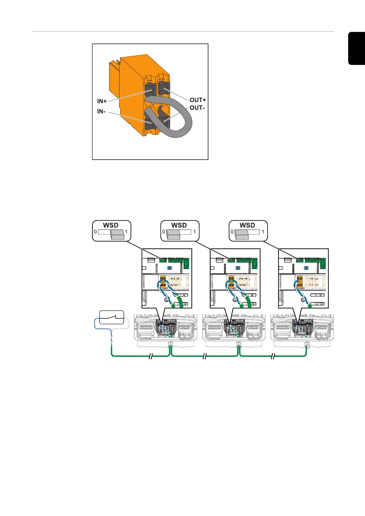
EasyManuals Logo

Fronius Symo GEN24 10.0 User Manual

Fronius Symo GEN24 10.0
192 pages
To Next Page IconTo Next Page
To Previous Page IconTo Previous Page
Page #93 background imageLoading...
Page #93 background image
Installing the
WSD (wired
shutdown)
IMPORTANT!
The push-in WSD terminal in the in-
verter's connection area is delivered
with a bypass ex works as standard.
The bypass must be removed when in-
stalling a trigger device or a WSD
chain.
The WSD switch of the first inverter with connected trigger device in the WSD
chain must be in position 1 (primary device). The WSD switch of all other invert-
ers should be in the 0 (secondary device) position.
Max. distance between two devices: 100 m
Max. number of devices: 28
IN (+)
IN (-)
OUT (+)
OUT (-)
IN (+)
IN (-)
OUT (+)
OUT (-)
IN (+)
IN (-)
OUT (+)
OUT (-)
CAT 5/6/7
*
* Floating contact of the trigger device (e.g. central grid and system protection).
If several floating contacts are used in a WSD chain, they must be connected in
series.
93
EN

Table of Contents

Questions and Answers:

Question and Answer IconNeed help?

Do you have a question about the Fronius Symo GEN24 10.0 and is the answer not in the manual?

Fronius Symo GEN24 10.0 Specifications

General IconGeneral
ModelFronius Symo GEN24 10.0
CategoryInverter
AC nominal output10.0 kW
AC grid frequency50 Hz / 60 Hz
THD< 3 %
Number of MPP trackers2
Protection classIP66
AC Nominal Voltage230 V / 400 V
Operating Temperature Range-25°C to +60°C
Max. apparent AC power10, 000 VA
AC nominal voltage range230 V
DC connection4x DC+ and 4x DC- screw terminals
Maximum AC Power10000 VA
Maximum DC Power15 kW
AC Voltage Range180 - 280 V
CoolingActive cooling
Warranty5 years

Related product manuals