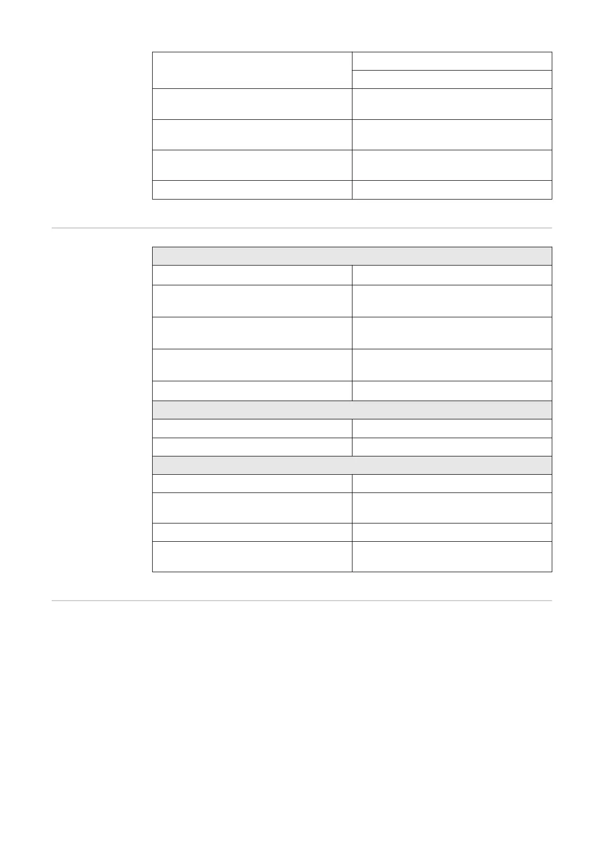
Voltage level of digital inputs
low: min. 0 V–max. 1.8 V
high: min. 4.5 V–max. 28.8 V
Input currents of digital inputs depending on the input voltage;
input resistance = 70 kOhm
Total power for digital output (for in-
ternal supply)
6 W at 12 V (USB not connected)
Power per digital output
(for external supply)
1 A at >12.5 V-24 V
(max. 3 A in total)
Datalogger/web server Integrated
Technical data of
surge protective
device DC SPD
type 1+2 GEN24
General data
Continuous operating current (I
cpv
) < 0.1 mA
Rated discharge current (I
n
)
- 15 x 8/20 µs pulses
20 kA
Lightning surge current (l
imp
)
Max. discharge capacity @ 10/350 µs
6.25 kA
Protection level (U
p
)
(star-shaped mounting)
4 kV
Short-circuit strength PV (I
scpv
) 15 kA
Disconnector
Thermal disconnector Integrated
External fuse None
Mechanical properties
Disconnection indicator Mechanical indicator (red)
Remote communication of the con-
nection interruption
Output on the changeover contact
Housing material Thermoplastic UL-94-V0
Test standards IEC 61643-31 / DIN EN 50539-11
UL1449 ed.4 / VDE 0185-305-3 Bbl. 5
Explanation of
footnotes
1) The values stated are defaults; the inverter is configured specifically to
suit the requirements of the relevant country.
2) Depending on the country setup or device-specific settings
(ind. = inductive; cap. = capacitive).
3) Maximum current from a defective PV module to all other PV modules.
From the inverter itself to one PV side of the inverter, it is 0 A.
4) Guaranteed by the electrical configuration of the inverter.
5) For backup power mode (PV Point) without battery, a minimum voltage of
150 V is required.
6) Current peak when switching on the inverter.
7) The sum of the rated power per phase must not exceed the rated power of
the inverter.
170
 Loading...


