Installation location and position
Choosing the
location of the
inverter
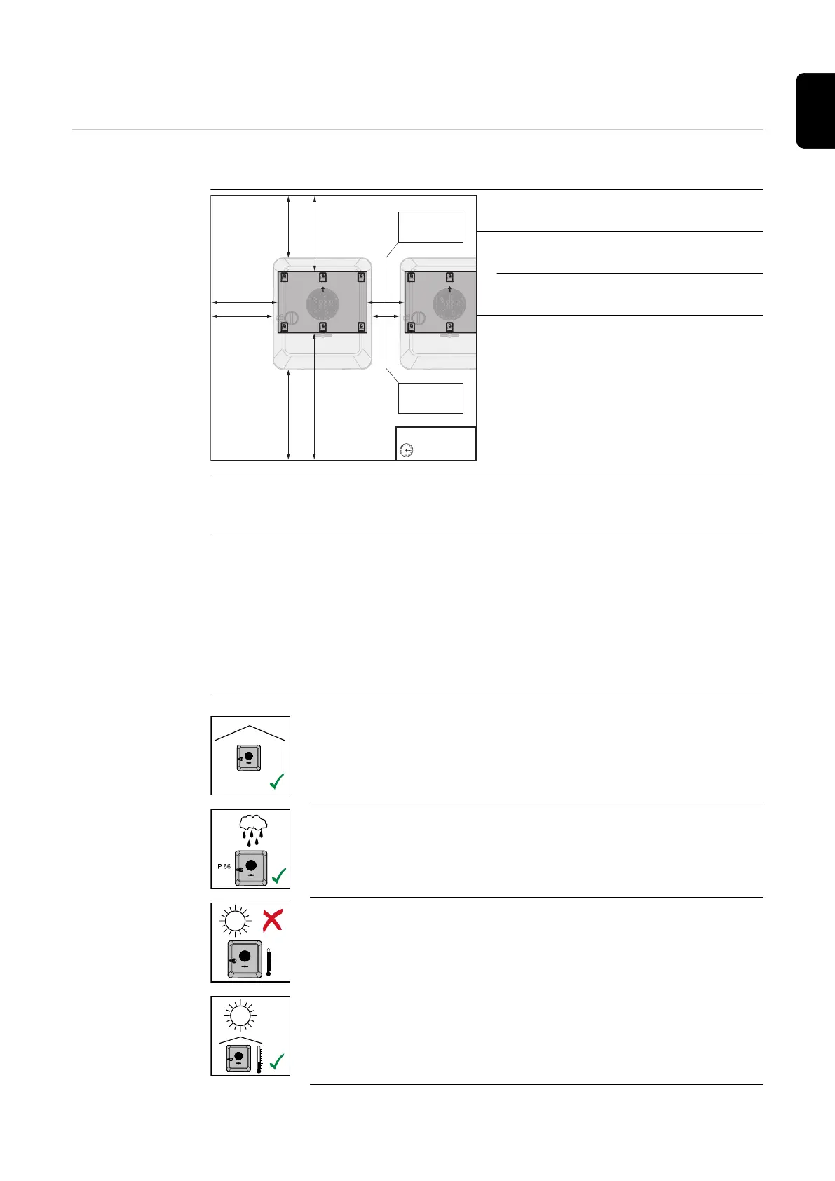
Please note the following criteria when choosing a location for the inverter:
≥ 200 mm
(≥ 7.87 inch)
≥ 200 mm
(≥ 7.87 inch)
≥ 445 mm
(≥ 17.52 inch)
≥ 250 mm
(≥ 9.84 inch)
≥ 225 mm
(≥ 8.86 inch)
≥ 275 mm
(≥ 10.83 inch)
≥ 150 mm
(≥ 5.91 inch)
≥ 100 mm
(≥ 3.94 inch)
-25°C - +60°C
0 - 100%
Only install on a solid, non-flam-
mable surface.
Max. ambient temperatures:
-25 °C - +60 °C
Relative humidity:
0 - 100%
If the inverter is installed in a switch
cabinet or similar enclosed space,
ensure sufficient heat dissipation
with forced-air ventilation.
For detailed information on the di-
mensions of the inverter, see chapter
Fronius Symo GEN24 6 - 10 kW on
page 189.
When installing the inverter on the outer walls of cattle sheds, it is important
to keep a minimum clearance of 2 m between all sides of the inverter and air
vents and building openings.
The following substrates are permissible for installation:
-
Walls (corrugated metal walls [mounting rails], brick walls, concrete walls,
or other non-flammable surfaces sufficiently capable of bearing loads)
-
Poles (installed using mounting rails, behind the PV modules directly on
the PV mounting system)
-
Flat roofs (if this is for a film roof, make sure that the films comply with
the fire protection requirements and are not highly flammable. Ensure
compliance with the national provisions.)
-
Covered car park roofs (no overhead installation)
The inverter is suitable for indoor installation.
The inverter is suitable for outdoor installation.
Because of its IP 66 protection class, the inverter is resistant to
water jets from any direction and can also be used in damp en-
vironments.
In order to minimise the heating up of the inverter, do not ex-
pose it to direct insolation. The inverter should be installed in a
protected location, for example, below the PV modules or under
an overhanging roof.
55
EN
 Loading...


