The various operating modes
Operating modes
– Explanation of
symbols
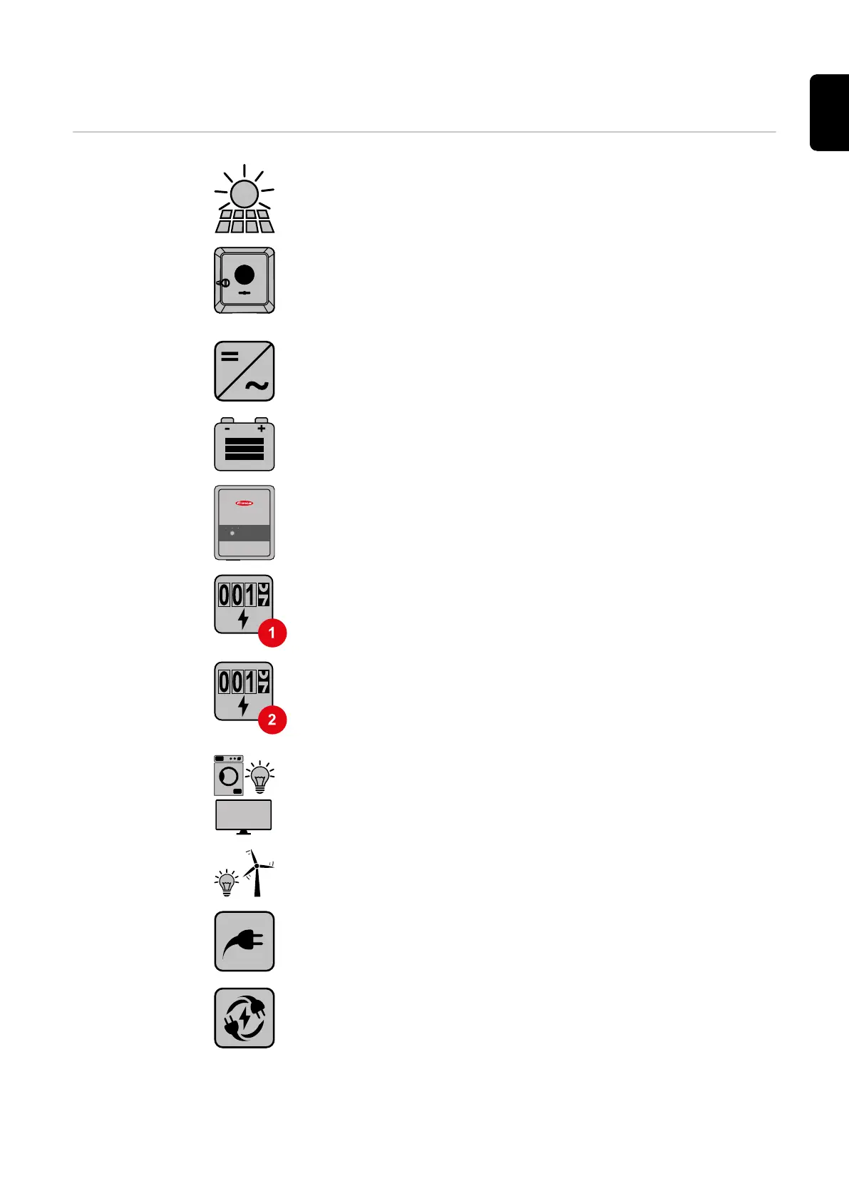
PV module
generates direct current
Fronius GEN24 inverter
converts direct current into alternating current and charges the
battery (battery charging is only possible with Fronius GEN24 Plus
inverters). The integrated system monitoring enables the inverter
to be integrated into a network by means of WLAN.
Additional inverter in the system
converts the direct current into alternating current. However, it
cannot charge a battery, and is not available in backup power
mode.
Battery
is coupled to the inverter on the direct current side, and stores
electrical energy.
Fronius Ohmpilot
for using excess energy to heat water.
Primary meter
records the system's load curve and provides measurement data
for energy profiling in Fronius Solar.web. The primary meter also
controls the dynamic feed-in control.
Secondary meter
records the load curve of individual loads (e.g. washing machine,
lamps, TV, heat pump, etc.) in the consumption branch and
provides measurement data for energy profiling in Fronius Sol-
ar.web.
Loads in the PV system
are the loads connected in the system.
Additional loads and generators in the system
are connected to the system by means of a utility meter.
PV Point
is a non-uninterruptible single-phase backup power circuit which
supplies electrical devices with up to 3 kW if sufficient power is
available from the PV modules or the battery.
Full Backup
the inverter is prepared for backup power mode. The backup
power mode must be implemented in the switch cabinet by the
electrician performing the installation. The PV system operates in
a stand-alone manner in backup power mode.
19
EN
 Loading...


