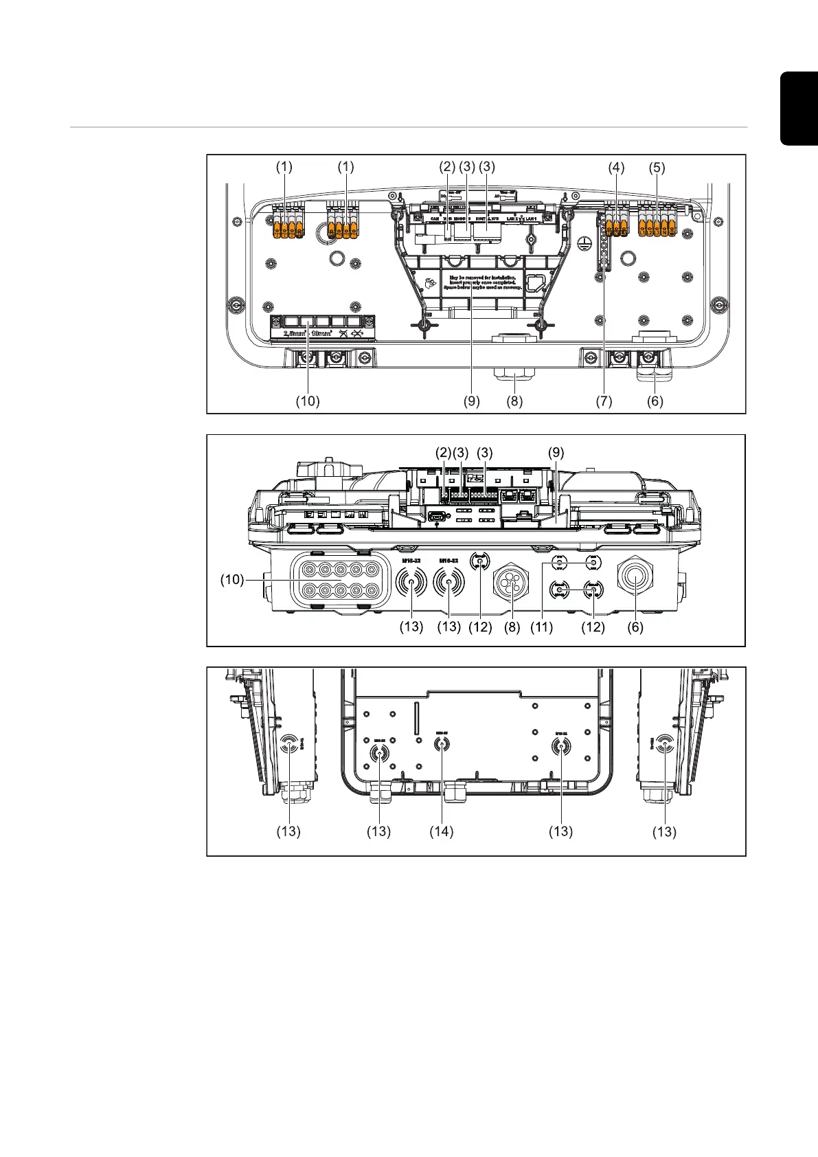
Control elements and connections
Connection area
(1) 2 x 4-pin DC push-in terminal
(2) Push-in WSD (wired shutdown) terminal
(3) Push-in terminals in the data communication area (Modbus, digital inputs
and outputs)
(4) 3-pin push-in terminal for PV Point (OP)
(5) 5-pin AC push-in terminal
(6) Cable gland/strain-relief device AC
(7) 6-pin ground electrode terminal
(8) Cable gland/strain-relief device in the data communication area
31
EN
 Loading...


