(9) Connection area divider
(10) 10 x DC cable glands
(11) Optional cable gland (M16)
(12) Optional cable gland (M16 - M20)
(13) Optional cable gland (M16 - M32)
(14) Optional cable gland (M16 - M25)
Connection area
divider
The connection area divider separates the high-voltage conductors (DC and AC)
from the signal lines. To make it easier to reach the connection area, the divider
can be removed for the connection work, and must be re-inserted.
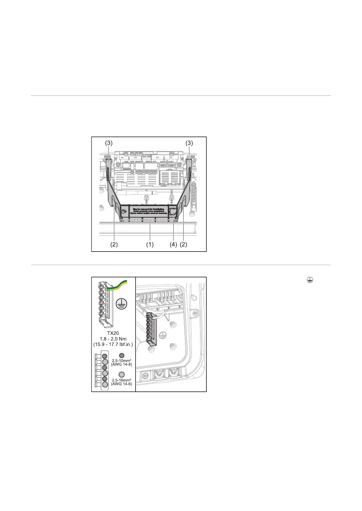
(1) Integrated cable duct
(2) Recesses for removing the con-
nection area divider
(3) Snap tabs for locking/unlocking
(4) Defined breaking point for the
Datcom connection
The integrated cable duct (1) allows for
the lines to be laid from one area of
the inverter to the other. As a result,
multiple inverters can be easily in-
stalled next to each other.
Ground elec-
trode terminal
The ground electrode terminal Al-
lows additional components to be
earthed, such as:
-
AC cable
-
Module mounting system
-
Ground rod
32
 Loading...


