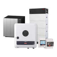
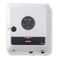
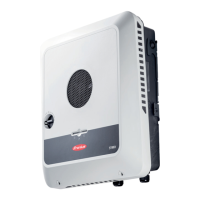
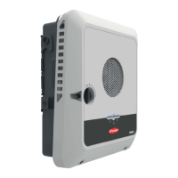
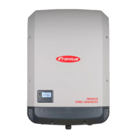
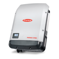
Do you have a question about the Fronius Symo GEN24 3.0 and is the answer not in the manual?
Explains the meaning of warning symbols and notices used in the manual.
Covers general safety standards, qualified personnel, and operational risks.
Details environmental conditions, personnel qualifications, and noise emission.
Covers EMC measures, backup power safety, and protective earthing.
Information on user data, copyright, and device notices.
Introduces the inverter's device concept, function overview, and components.
Describes various operating modes, symbols, states, and energy saving mode.
Details suitable batteries for the inverter and their connection.
Outlines manual system start, shutdown notifications, and protection strategies.
Details connection areas, terminals, and specific components like DC disconnector.
Explains button functions, LED status indicators, and sensor functions.
Shows the internal schematic connection diagram for the inverter's IO ports.
Explains the PV Point's role, voltage, current, and backup operation.
Covers specific operational aspects, limitations, and potential issues of the PV Point.
Discusses quick-lock system, warning notices, and component compatibility.
Provides criteria for location, mounting, electrical connections, and cable specs.
Covers connecting to the grid, solar modules, and batteries, including safety.
Provides safety guidelines and installation notes for the PV Point backup power connection.
Details data communication setup, Modbus, WSD installation, and cable routing.
Steps for closing the inverter covers and initial commissioning procedures.
Covers user login, language, device configuration, and component setup.
Explains load management, DRM, backup power, inverter parameters, and energy management.
Explains how PV power is reduced and how load management priorities are set.
Details system name, time sync, updates, setup wizard, and factory resets.
Covers license file management, online/offline licensing, and support options.
Details LAN, WLAN, Modbus, and remote control communication settings.
Information on surge protective devices, their function, and connection.
Details the DC connector kit for high current PV strings and its installation.
Provides general guidance on inverter operation, maintenance, cleaning, and safety.
Covers proper disposal of the inverter and packaging materials.
Information on manufacturer's warranty and registration.
Lists technical DC input specifications for the 3.0/3.0 Plus models.
Provides general inverter data, protection device specs, and data communication interfaces.
Lists technical DC input specifications for the 4.0/4.0 Plus models.
Lists technical DC input specifications for the 5.0/5.0 Plus models.
Details WLAN specifications and technical data for surge protective devices.
Provides general data and operating capacities for the integrated DC disconnector.
Shows the circuit diagram for the PV Point backup power variant.
Presents the circuit diagram for the PV Point (OP) variant for Australia.
Illustrates the circuit diagram for connecting the inverter with BYD battery systems.
Shows circuit diagrams for connecting multiple BYD batteries in parallel.
Displays the circuit diagram for connecting the inverter with LG RESU FLEX batteries.
Provides the wiring diagram for integrating surge protective devices.
| Category | Inverter |
|---|---|
| Output Power | 3.0 kW |
| Protection Rating | IP66 |
| Max. apparent AC power | 3.0 kVA |
| THD | < 3 % |
| Number of MPP trackers | 2 |
| Max. DC power | 4.5 kW |
| Model | Symo GEN24 3.0 |
| Communication Interfaces | Ethernet, Wi-Fi |
| AC grid connection | Single-phase |
| Battery voltage range | 40 V - 56 V |
| Max. charging / discharging power | 3 kW |
| Operating Temperature Range | -25°C - +60°C |
