Connecting the data communication cable
Modbus parti-
cipants
The inputs M0 and M1 can be selected for this purpose. A maximum of 4 Modbus
participants can be connected to the Modbus terminal on inputs M0 and M1.
IMPORTANT!
Only one primary meter, one battery and one Ohmpilot can be connected per in-
verter. Due to the high data transfer of the battery, the battery occupies 2 parti-
cipants. If the "Inverter control via Modbus" function is activated in the "Com-
munication” → "Modbus" menu, no Modbus participants are possible. It is not
possible to send and receive data at the same time.
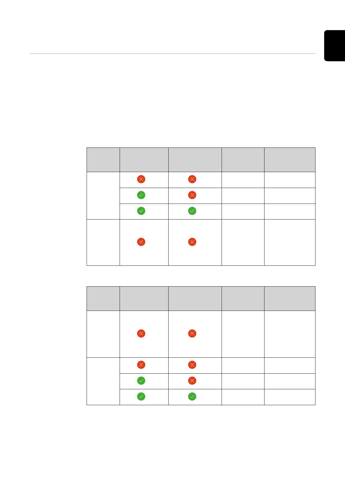
Example 1:
Input Battery
Fronius
Ohmpilot
Quantity
Primary
meter
Quantity
Secondary
meter
Modbus 0 (M0)
0 4
0 2
0 1
Modbus 1 (M1)
1 3
Example 2:
Input Battery
Fronius
Ohmpilot
Quantity
Primary
meter
Quantity
Secondary
meter
Modbus 0 (M0)
1 3
Modbus 1 (M1)
0 4
0 2
0 1
71
EN

 Loading...


