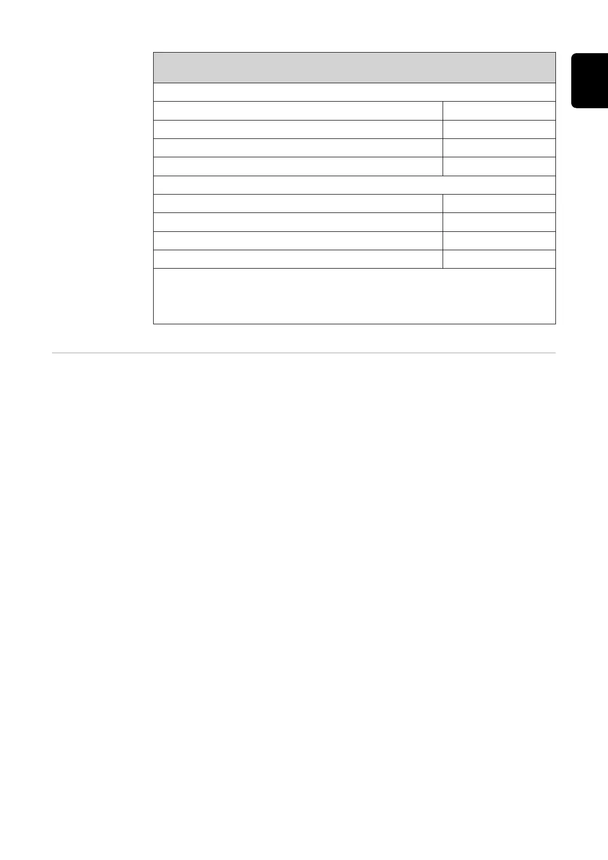
Example: Feed-in limitation
(without consideration of the efficiency)
Case 1: The battery can be charged
Power at grid feed-in point 1000 W
Power at inverter output 1000 W
Power into the battery 3000 W
Case 2: The battery cannot be charged
Power at grid feed-in point 3000 W
Power at inverter output 4000 W
Power into the battery 0 W
In this example, no more than 3000 W may be fed into the public grid at the
grid feed-in point. However, any loads that are located between the inverter
and the grid feed-in point can be supplied by additional power from the invert-
er.
Dynamic power
regulation with
several inverters
Example 1: Fronius SnapINverter ≤ Fronius Symo GEN24
Only 1 primary meter is required for the Fronius Symo GEN24 inverter.
The power values shown are an example. Inverter configurations with power val-
ues other than those shown in the example are possible, taking into account the
criteria for this example.
IMPORTANT!
Zero feed-in is not possible when using 2 inverters.
105
EN

 Loading...


