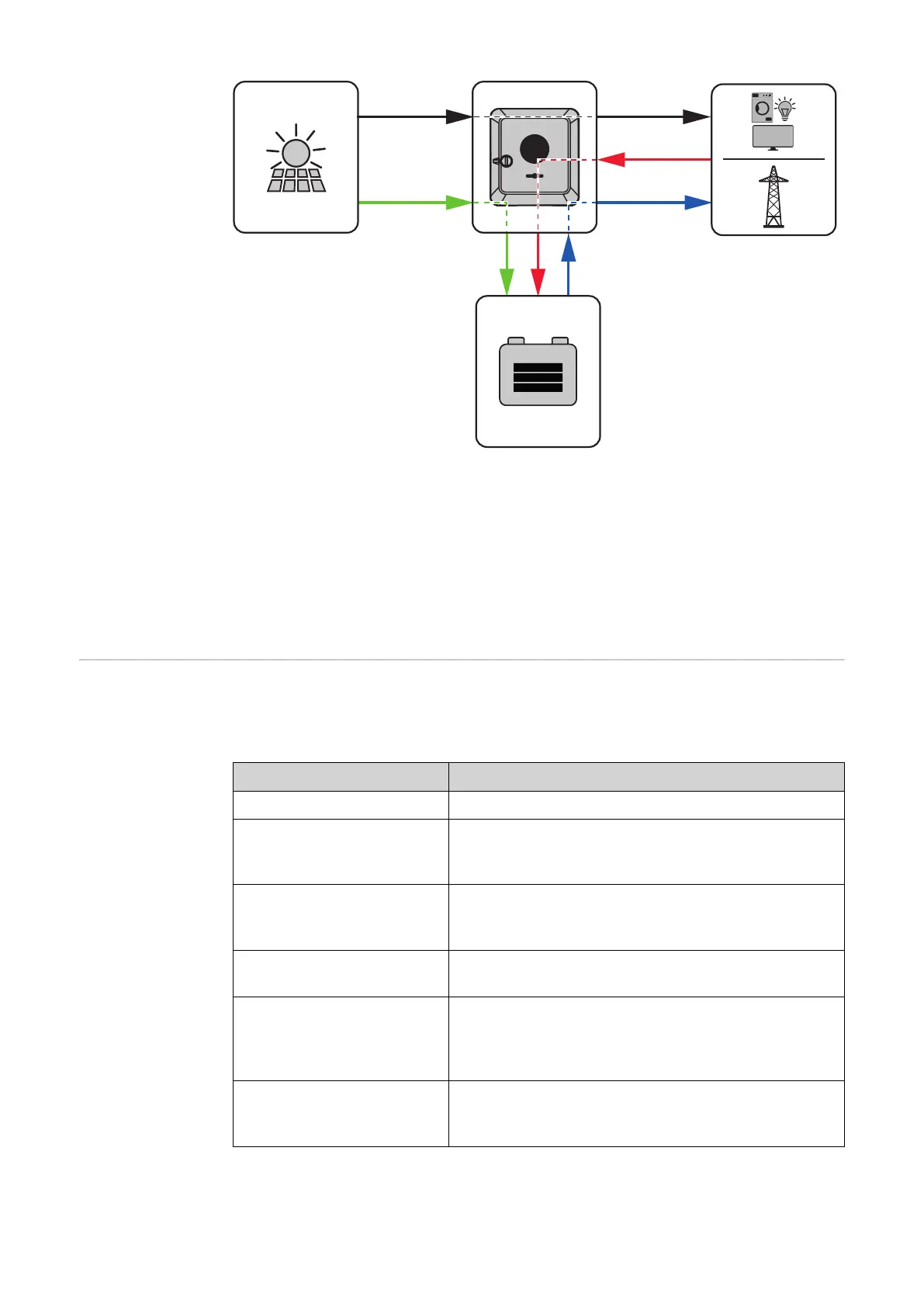
(1) PV module – inverter – load/grid
(2) PV module – inverter – battery*
(3) Battery – inverter – load/grid*
(4) Grid – inverter – battery*
* depending on the settings and local standards and regulations.
Operating states
(only for systems
with a battery)
Battery systems distinguish different operating states. In this case, the relevant
current operating state is displayed on the user interface of the inverter or in
Solar.web.
Operating state Description
Normal operation Energy is stored or drawn, as required.
Min. state of charge (SOC)
achieved
Battery has reached the minimum SOC set or
specified by the manufacturer. The battery cannot
be discharged any further.
Energy saving mode
(standby)
The system has been put into energy saving mode.
Energy saving mode is automatically ended as
soon as sufficient excess energy is available again.
Start The storage system starts from energy saving
mode (standby).
Forced re-charging The inverter re-charges the battery, in order to
maintain the set minimum SOC (state of charge)
or the SOC specified by the manufacturer (pro-
tection against deep discharge).
Deactivated The battery is not active. It has either been deac-
tivated/switched off, or an error means that no
communication with the battery is possible.
20

 Loading...


