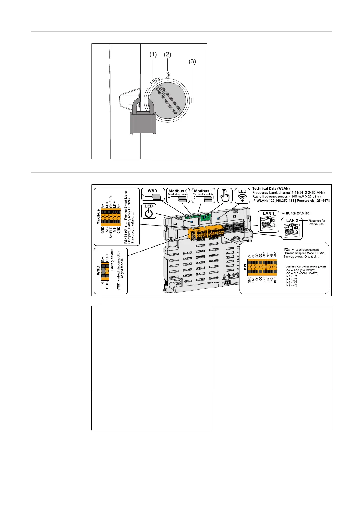
DC disconnector The DC disconnector has 3 switch set-
tings:
(1) Locked/off (turned to the left)
(2) Off
(3) On
IMPORTANT!
In switch settings (1) and (3), a conven-
tional padlock can be used to secure
the inverter against being switched on/
off. The national guidelines must be
complied with in this respect.
Data communic-
ation area
Modbus terminal Push-in terminal for the installation of
Modbus 0, Modbus 1, 12 V and GND
(ground).
The data connection to the connected
components is established via the
Modbus terminal. The inputs M0 and
M1 can be selected for this purpose.
Max. 4 Modbus participants per input,
see chapter Modbus participants on
page 71.
WSD (wired shutdown) switch Defines the inverter as a WSD primary
device or WSD secondary device.
Position 1: WSD primary device
Position 0: WSD secondary device
30

 Loading...


