General
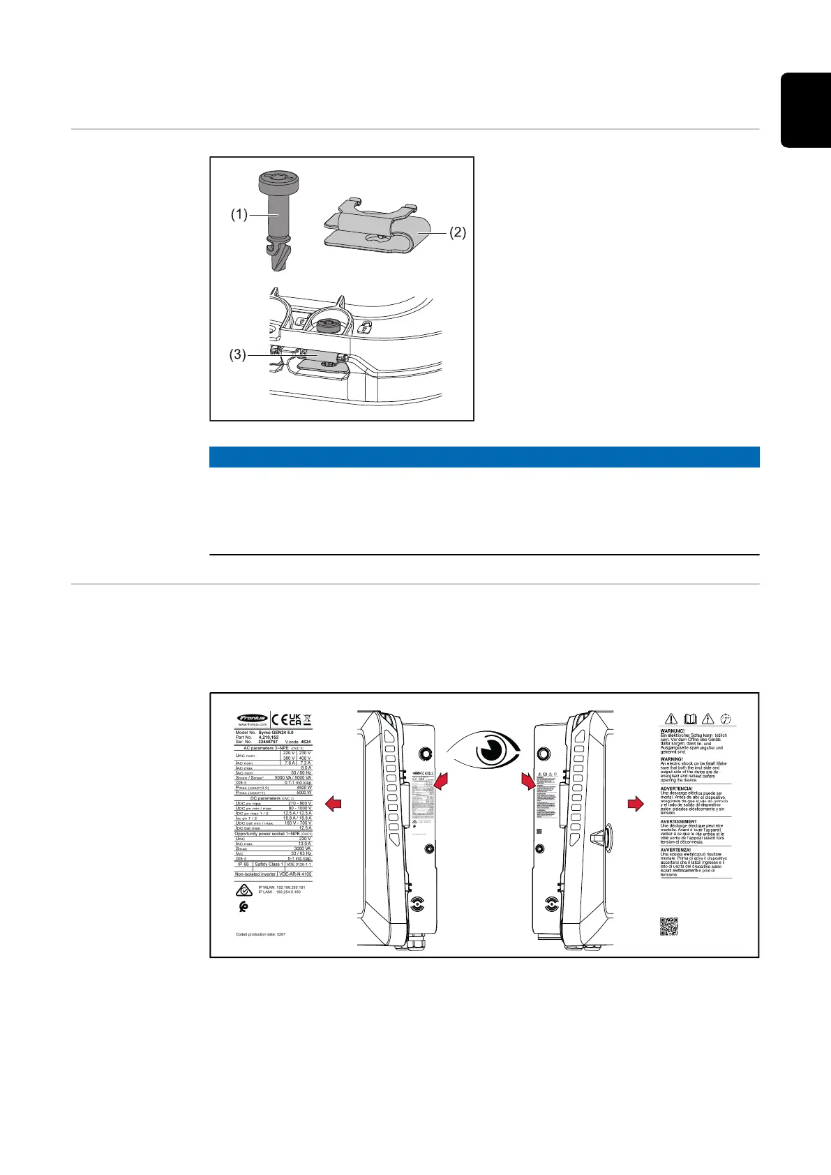
Quick-lock sys-
tem
A quick-lock system (3) is used to
mount the connection area cover and
front cover. The system is opened and
closed with a half-rotation (180°) of
the captive screw (1) into the quick-
lock spring (2).
The system is independent of torque.
NOTE!
Danger when using a drill driver.
This may result in the destruction of the quick-lock system due to overtorque.
▶
Use a screwdriver (TX20).
▶
Do not turn the screws more than 180°.
Warning notices
on the device
Technical data, warning notices and safety symbols are affixed to the inverter.
These warning notices and safety symbols must not be removed or painted over.
They warn against incorrect operation which can lead to serious injury and dam-
age.
A 4-digit number (coded production date) is printed on the rating plate at the
very bottom, from which the production date can be calculated.
If you subtract the value 11 from the first two digits, you get the production year.
The last two digits stand for the calendar week in which the device was produced.
Example:
Value on rating plate = 3207
41
EN

 Loading...


