The various operating modes
Operating modes
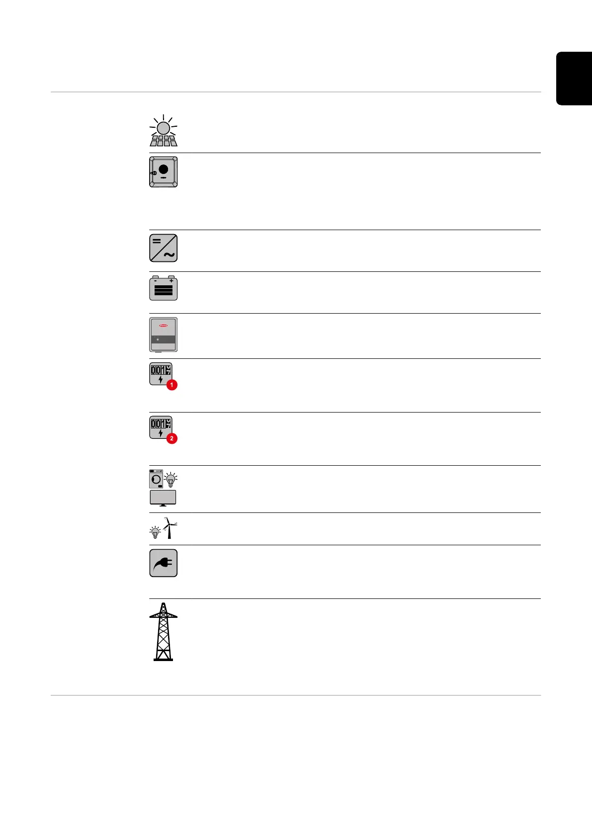
– Explanation of
symbols
PV module
generates direct current
Fronius GEN24 inverter
converts direct current into alternating current and charges the bat-
tery (charging the battery is dependent on the device variant, suitable
batteries, the requisite cabling and settings). The integrated system
monitoring enables the inverter to be integrated into a network by
means of WLAN.
Additional inverter in the system
converts the direct current into alternating current. However, it can-
not charge a battery, and is not available in backup power mode.
Battery
is coupled to the inverter on the direct current side, and stores elec-
trical energy.
Fronius Ohmpilot
for using excess energy to heat water.
Primary meter
records the system's load curve and provides measurement data for
energy profiling in Fronius Solar.web. The primary meter also controls
the dynamic feed-in control.
Secondary meter
records the load curve of individual loads (e.g. washing machine,
lamps, TV, heat pump, etc.) in the consumption branch and provides
measurement data for energy profiling in Fronius Solar.web.
Loads in the PV system
are the loads connected in the system.
Additional loads and generators in the system
are connected to the system by means of a Smart Meter.
PV Point
is a non-uninterruptible 1‑phase backup power circuit which supplies
electrical devices with up to 3 kW if sufficient power is available from
the PV modules or the battery.
Grid
supplies the loads in the system if insufficient power is being gener-
ated by the PV modules or supplied by the battery.
Operating mode
– Inverter with
battery
In order to be able to obtain the highest rate of self-consumption with your PV
system, a battery can be used to store excess energy. The battery is coupled to
the inverter on the direct current side. Multiple current conversion is therefore
not required, and the efficiency is increased.
17
EN

 Loading...


