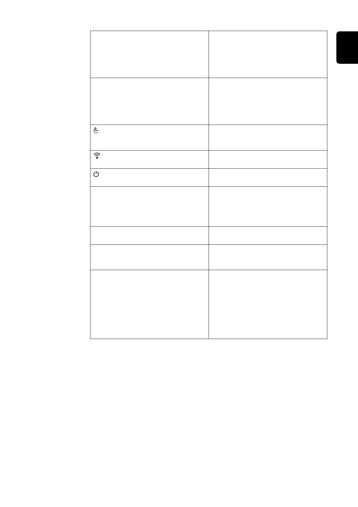
Modbus 0 (MB0) switch Switches the terminating resistor for
Modbus 0 (MB0) on/off.
Position 1: Terminating resistor on
(factory setting)
Position 0: Terminating resistor off
Modbus 1 (MB1) switch Switches the terminating resistor for
Modbus 1 (MB1) on/off.
Position 1: Terminating resistor on
(factory setting)
Position 0: Terminating resistor off
Optical sensor
To operate the inverter. See chapter
Button functions and LED status in-
dicator on page 32.
Communication LED
Indicates the inverter connection
status.
Operating status LED
Indicates the inverter operating
status.
LAN 1 Ethernet connection for data commu-
nication (e.g. WLAN router, home net-
work or for commissioning with a
laptop see chapter Installation using
the web browser on page 78).
LAN 2 Reserved for future functions. Only
use LAN 1 to avoid malfunctions.
WSD terminal Push-in terminal for the WSD installa-
tion. See chapter "WSD (wired shut-
down)" on page 27.
IOs terminal Push-in terminal for digital inputs/
outputs. See chapter Permitted
cables for the data communication
connection on page 49.
The designations (RG0, CL0, 1/5, 2/6,
3/7, 4/8) on the terminal refer to the
Demand Response Mode function, see
chapter Functions andI/Os on page
84.
31
EN

 Loading...


