Settings on the user interface of the Fronius Symo GEN24 inverter:
1
Configure the primary meter at the feed-in point in the "Device configura-
tion" → "Components" menu.
2
Activate the limit for the entire system in the "Safety and grid regulations" →
"Export limitation" menu. Enter the DC rated power of the entire PV system
in the "Total DC system power" input field. Enter the percentage value (50%,
60% or 70%) in the "Maximum permitted feed-in power of the entire system"
input field.
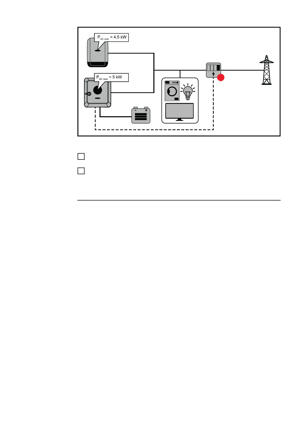
Example 2a: Fronius SnapINverter > Fronius Symo GEN24
Two primary meters are required for the inverters.
The power values shown are an example. Inverter configurations with power val-
ues other than those shown in the example are possible, taking into account the
criteria for this example.
IMPORTANT!
With two primary meters at the feed-in point without a secondary meter, Fronius
SnapINverter and Fronius Symo GEN24 inverters cannot be displayed as a com-
bined PV system in Solar.web. Two individual PV systems must be created in Sol-
ar.web.
106

 Loading...


