Settings on the user interface of the Fronius Symo GEN24 inverter:
1
Configure the primary meter at the feed-in point in the "Device configura-
tion" → "Components" menu.
Settings in the system monitoring of the Fronius SnapInverter:
1
Configure the primary meter at the feed-in point in the "Settings" → "Meter"
menu.
2
Activate the limit for the entire system in the "DNO Editor" → "Dynamic
power reduction" menu. Enter the DC rated power of the entire PV system in
the "Total DC system power" input field. Enter the percentage value (50%,
60% or 70%) in the "Max. grid feed-in power" input field.
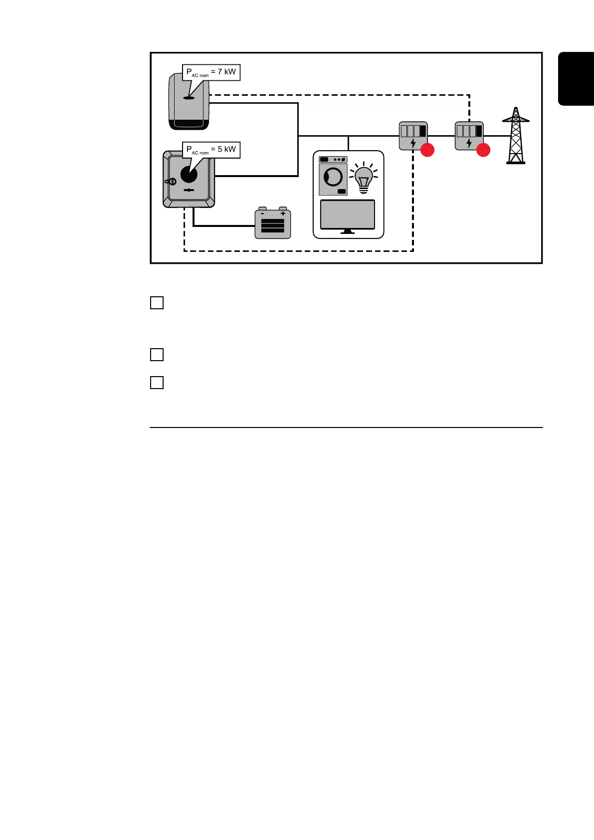
Example 2b: Fronius SnapINverter > Fronius Symo GEN24
Two primary meters and one secondary meter are required for the inverters.
The power values shown are an example. Inverter configurations with power val-
ues other than those shown in the example are possible, taking into account the
criteria for this example.
IMPORTANT!
In order to be able to record all PV system data in Solar.web in full, only the
Fronius Symo GEN24 inverter may be created in this PV system. The Fronius
SnapINverter data is transmitted from the secondary meter to the Fronius Symo
GEN24 inverter and thus displayed in Solar.web.
We recommend that you set up the Fronius SnapINverter as a separate addition-
al PV system in Solar.web for servicing and maintenance work (e.g. status codes,
online updates, etc.).
107
EN

 Loading...


