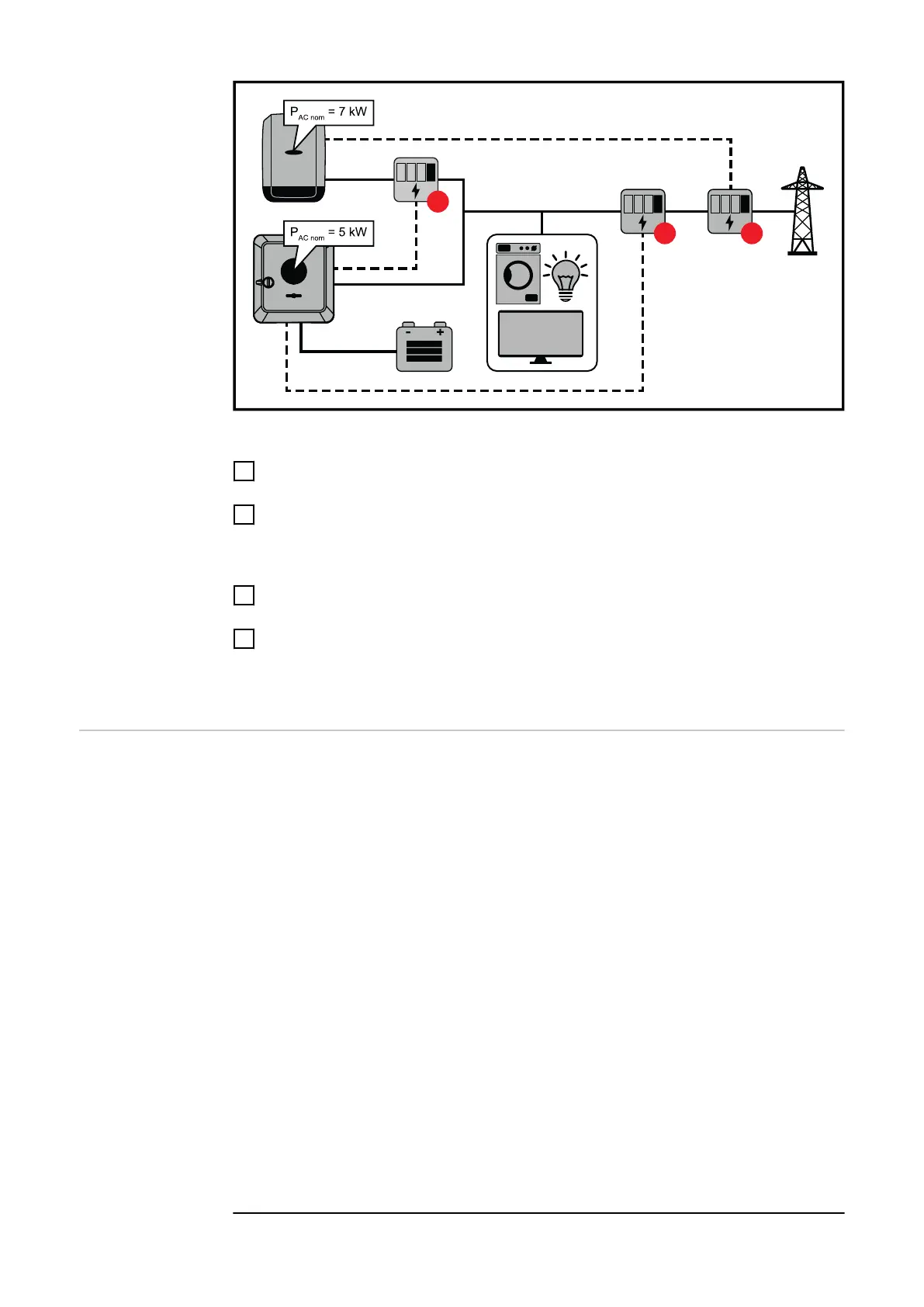
Settings on the user interface of the Fronius Symo GEN24 inverter:
1
Configure the primary meter at the feed-in point in the "Device configura-
tion" → "Components" menu.
2
Configure the secondary meter in the "Device configuration" → "Compon-
ents" menu.
Settings in the system monitoring of the Fronius SnapInverter:
1
Configure the primary meter at the feed-in point in the "Settings" → "Meter"
menu.
2
Activate the limit for the entire system in the "DNO Editor" → "Dynamic
power reduction" menu. Enter the DC rated power of the entire PV system in
the "Total DC system power" input field. Enter the percentage value (50%,
60% or 70%) in the "Max. grid feed-in power" input field.
I/O power man-
agement
General
In this menu item, settings relevant for a distribution network operator (DNO) are
made. An effective power limitation in % and/or a power factor limitation can be
set.
IMPORTANT!
The service password must be entered in order to adjust settings in this menu
item. Settings in this menu area must only be made by trained and qualified per-
sonnel.
"Input pattern" (assignment of individual I/Os)
1 click = white (contact open)
2 clicks = blue (contact closed)
3 x clicks = grey (not used)
"Power factor (cos φ)"
"ind" = inductive
"cap" = capacitive
"DNO feedback"
When the rule is enabled, output DNO feedback (pin 1 recommended) must be
configured (e.g. for operating a signalling device).
For "Import" or "Export", the data format *.fpc is supported.
108

 Loading...


