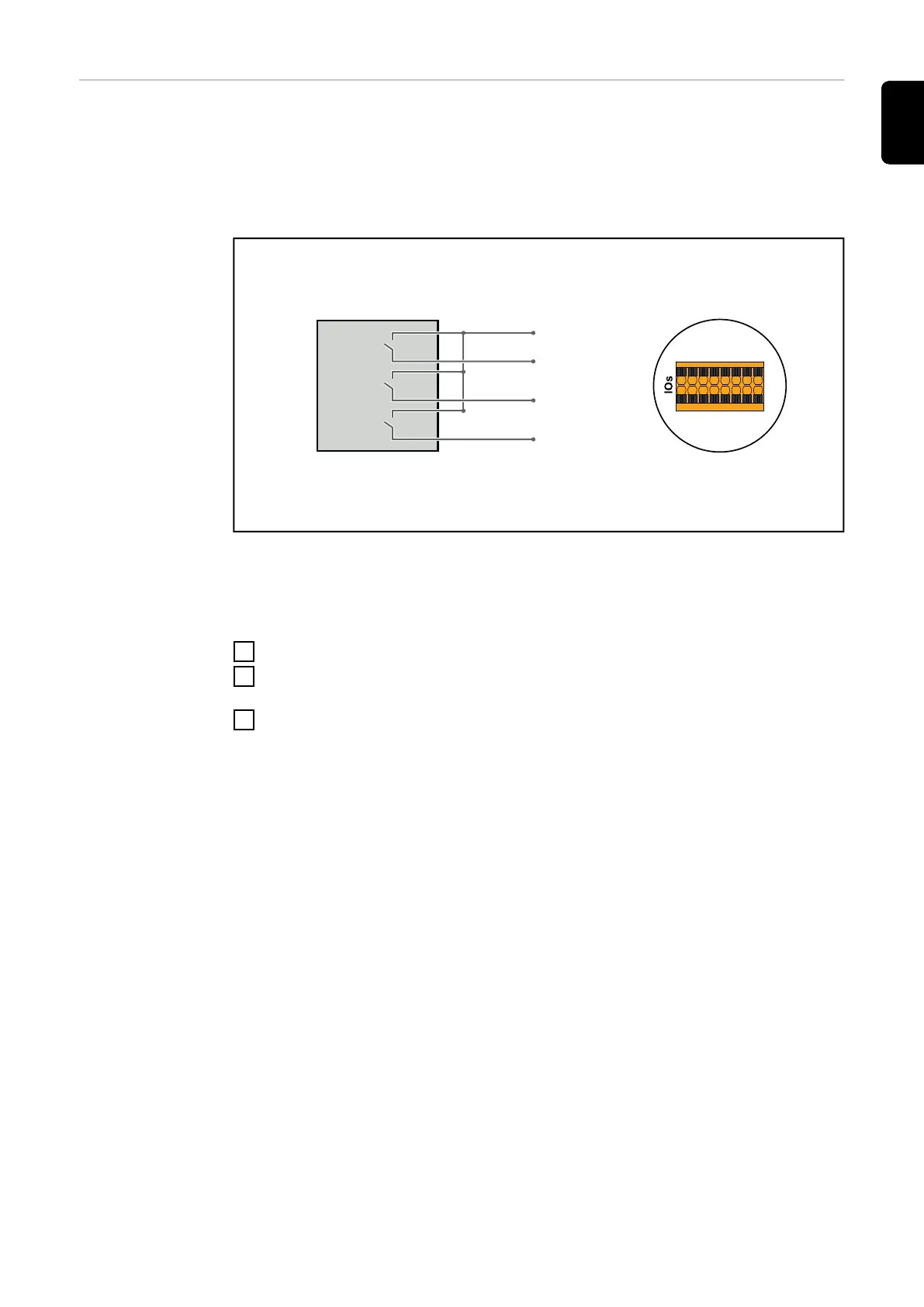
Connection dia-
gram - 3 relay
The ripple control signal receiver and the I/Os terminal of the inverter can be
connected to one another in accordance with the connection diagram.
If the distance between the inverter and the ripple control signal receiver ex-
ceeds 10 m, at least a CAT 5 cable is recommended and the shield must be con-
nected at one end to the push-in terminal of the data communication area
(SHIELD).
(2)
IO4
V+
V+
IO0
IO2
IN6
IN8
IN10IN11
IN9
IN7
IO5
IO3
IO1
GND
GND
60 %
30 %
0 %
(1)
V+
IN8
IN9
IN10
(1) Ripple control signal receiver with 3 relays, for effective power limiting.
(2) I/Os of the data communication area.
Use the preconfigured file for 3-relay mode:
1
Download the file (.fpc) under 3-relay mode onto the end device.
2
Upload the file (.fpc) in the "I/O Power Management" menu using the "Im-
port" button.
3
Click on the "Save" button.
The settings for 3-relay mode are stored.
131
EN
 Loading...


