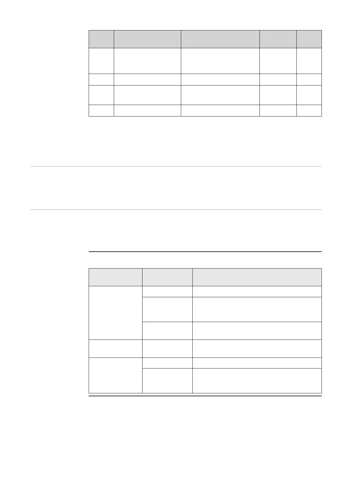
Mode Description Information DRM pin I/O
pin
DRM5 Export P
nom
≤ 0%
without disconnec-
tion from the grid
currently not supported DRM 1/5 IN6
DRM6 Export P
nom
≤ 50% currently not supported DRM 2/6 IN7
DRM7 Export P
nom
≤ 75% &
-Q
rel
* ≥ 0%
currently not supported DRM 3/7 IN8
DRM8 Export P
nom
≤ 100% currently not supported DRM 4/8 IN9
The percentages always refer to the nominal device output.
IMPORTANT!
If the Demand Response Mode (DRM) function is enabled and no DRM control is
connected, the inverter switches to Standby mode.
Demand Re-
sponse Modes
(DRM)
Here you can enter a value for the apparent power input and the apparent power
output for the Australia country setup.
Inverter "Enforce Standby"
When the function is activated, the feed-in mode of the inverter is interrupted.
This enables a powerless shutdown of the inverter and protects its components.
When the inverter is restarted, the standby function is automatically deactivated.
"PV 1" and "PV 2"
Parameter Range of val-
ues
Description
"Mode" Off The MPP tracker is deactivated.
Auto The inverter uses the voltage at which the
max. possible power of the MPP tracker is
possible.
Fix The MPP tracker uses the voltage defined
in the "UDC fix".
"UDC fix" 80 ‑ 530 V The inverter uses the fixed preset voltage
used at the MPP tracker.
"Dynamic Peak
Manager"
Off The function is deactivated.
On The entire solar module string is checked
for optimisation potential and determines
the best possible voltage for feed-in mode.
"Ripple Control"
Ripple control signals are signals sent out by the energy company to switch con-
trollable loads on and off. Depending on the installation situation, ripple control
106
 Loading...


