4
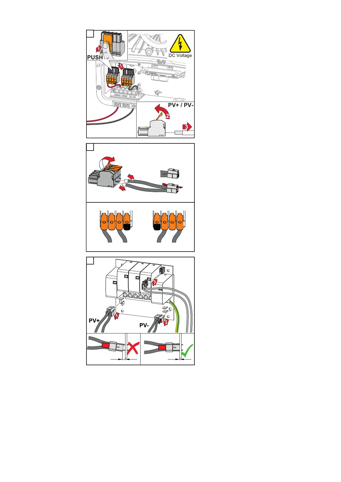
Remove the DC push-in terminals from
the slots and disconnect them from
the cables (only necessary if the in-
stallation already exists).
P
V1-
PV2-
PV2+
PV1+
3
PV1
+
PV1
+
PV2
+
BAT
+
PV2
-
BAT
-
PV1
-
PV1
-
PV+
1
2
PV-
5
Connect the supplied PV+/PV- cables
to the respective connections.
IMPORTANT!
Note the labelling of the cables when
connecting.
6
Connect the supplied cables to the re-
spective connections on the PC board.
IMPORTANT!
The plugs must be connected onto the
PC board as far as they will go.
144
 Loading...


