EasyManuals Logo

Fronius Symo GEN24 10.0 User Manual

Fronius Symo GEN24 10.0
192 pages
To Next Page IconTo Next Page
To Previous Page IconTo Previous Page
Page #145 background imageLoading...
Page #145 background image
7
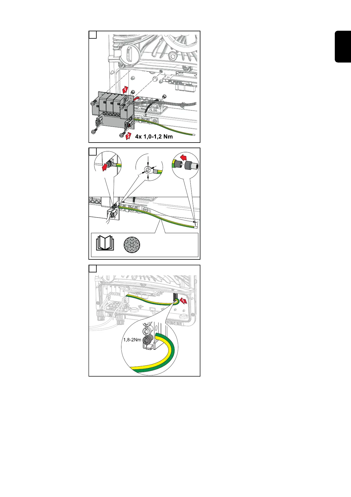
Insert the PC board into the inverter
and secure with the four screws (TX20)
supplied at a torque of 1.0 1.2 Nm.
§
National Standards
2
1
0
m
m
min. 6mm² - max. 16mm²
CU-Wire
min. 75°C / 167°F
1,5 Nm
TX 20
Ø10mm
max.
Ø4
m
m
8
IMPORTANT!
Depending on national standards and
guidelines, a larger cross section of the
ground conductor may be required.
Dimension the cable cross section of
the ground conductor according to the
national standards and guidelines and
fit a ring cable lug (inner diameter:
4 mm, outer diameter: max. 10 mm) as
well as a corresponding ferrule. Fasten
the ground conductor to the PC board
with a torque of 1.5 Nm.
9
Fasten the ground conductor to the
first input from the bottom of the
ground electrode terminal using a
screwdriver (TX20) and a torque of 1.8
- 2 Nm.
IMPORTANT!
The use of other inputs can make it
difficult to insert the connection area
divider or damage the ground conduct-
or.
145
EN

Table of Contents

Questions and Answers:

Question and Answer IconNeed help?

Do you have a question about the Fronius Symo GEN24 10.0 and is the answer not in the manual?

Fronius Symo GEN24 10.0 Specifications

General IconGeneral
ModelFronius Symo GEN24 10.0
CategoryInverter
AC nominal output10.0 kW
AC grid frequency50 Hz / 60 Hz
THD< 3 %
Number of MPP trackers2
Protection classIP66
AC Nominal Voltage230 V / 400 V
Operating Temperature Range-25°C to +60°C
Max. apparent AC power10, 000 VA
AC nominal voltage range230 V
DC connection4x DC+ and 4x DC- screw terminals
Maximum AC Power10000 VA
Maximum DC Power15 kW
AC Voltage Range180 - 280 V
CoolingActive cooling
Warranty5 years

Related product manuals