EasyManuals Logo

Fronius Symo GEN24 10.0 User Manual

Fronius Symo GEN24 10.0
192 pages
To Next Page IconTo Next Page
To Previous Page IconTo Previous Page
Page #146 background imageLoading...
Page #146 background image
10
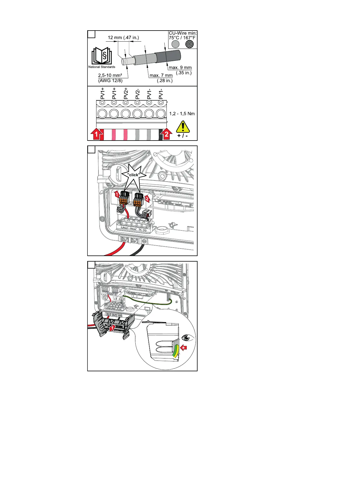
Strip the insulation on the single con-
ductors by 12 mm and secure to the
corresponding slot of the terminal on
the PC board with a torque of 1.2 - 1.5
Nm.
IMPORTANT!
The cable cross-section must be selec-
ted according to the specifications for
the respective inverter power category
(see chapter Permitted cables on page
61).
11
Push the DC push-in terminals into the
corresponding slot until there is an
audible click.
12
Re-insert the connection area divider.
* Lay the ground conductor in the in-
tegrated cable duct.
IMPORTANT!
When inserting the connection area di-
vider, be careful not to kink, pinch,
crush or otherwise damage the ground
conductor.
146

Table of Contents

Questions and Answers:

Question and Answer IconNeed help?

Do you have a question about the Fronius Symo GEN24 10.0 and is the answer not in the manual?

Fronius Symo GEN24 10.0 Specifications

General IconGeneral
ModelFronius Symo GEN24 10.0
CategoryInverter
AC nominal output10.0 kW
AC grid frequency50 Hz / 60 Hz
THD< 3 %
Number of MPP trackers2
Protection classIP66
AC Nominal Voltage230 V / 400 V
Operating Temperature Range-25°C to +60°C
Max. apparent AC power10, 000 VA
AC nominal voltage range230 V
DC connection4x DC+ and 4x DC- screw terminals
Maximum AC Power10000 VA
Maximum DC Power15 kW
AC Voltage Range180 - 280 V
CoolingActive cooling
Warranty5 years

Related product manuals