13
EN
String fuses are used in the Fronius Eco to provide additional protection for the solar mod-
ules.
The maximum short circuit current I
sc
, the maximum module return current I
R
or the maxi-
mum string fuse rating specified in the module data sheet of the respective solar module
is crucial in affording the solar modules the correct fuse protection.
The maximum short circuit current I
SC
per terminal is 15 A.
Where necessary, a tripping current higher than 15 A may be selected for the string fuses.
A DC Connector Kit (item number: 4,251,015) must be used if the inverter is operated with
an external string combiner box. In this case the solar modules are protected externally in
the string combiner box, and the metal bolts need to be used in the inverter.
The national regulations in respect of fuse protection must be observed. The electrical en-
gineer carrying out the installation is responsible for the correct choice of string fuses.
As an option, the inverter can be supplied with the following fuses:
- 6 x 15 A string fuses on the DC+ input and 6 x metal pins on the DC- input
- 12 x metal pins
Criteria for select-
ing the right
string fuses
The following criteria must be met for each solar module string when selecting suitable fus-
es:
-I
N
> 1.8 x I
SC
-I
N
< 2.4 x I
SC
-U
N
>/= max. input voltage of the inverter used
- Fuse dimensions: diameter 10 x 38 mm
I
N
Nominal current of fuse
I
SC
Short circuit current for standard test conditions (STC) according to the solar mod-
ule data sheet
U
N
Rated voltage of fuse
NOTE! To avoid the risk of a fire, only replace faulty fuses with new ones of the
same rating.
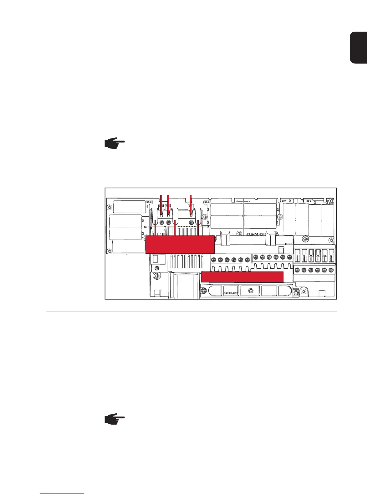
Option DC OVP
DC+ 2.1
DC+ 1.1
DC+ 1.3
DC+ 1.2
DC+ 2.3
DC+ 2.2
DC- 1.2
DC- 1.1
DC- 1.3
DC- 2.1
DC- 2.2
DC- 2.3
Do not remove cover!
NOTE! The nominal current rating of the fuse must not exceed the maximum fuse
protection specified in the data sheet supplied by the solar module manufacturer.
If a maximum fuse protection is not specified, then this information must be re-
quested from the solar module manufacturer.

 Loading...