77
EN
Undo the screws (2 x) and clamping
nut (size 30) on the strain-relief device
Insert the mains cable into the strain-
relief device
Tighten the clamping nut (size 30 mm)
Tighten the screws (2 x)
Connect the mains cable to the block
terminal correctly:
– PE conductor (green, or green
with yellow stripes) to the PE con-
nection
– Phase conductors to connections
L1 - L3
Replace the left side panel of the pow-
er source
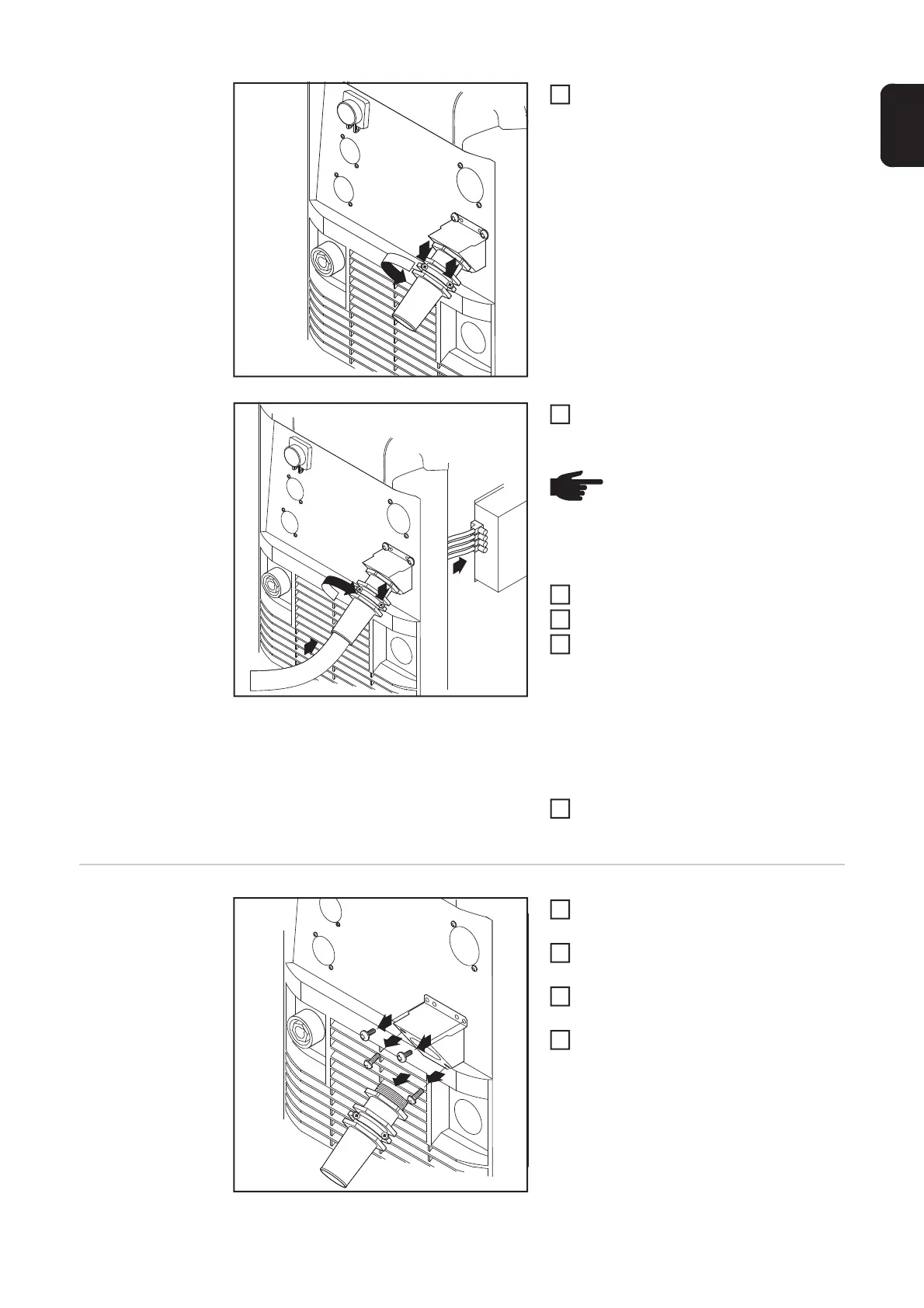
Replacing the
strain-relief de-
vice
Remove the left side panel of the pow-
er source
Remove the screws (2 x) from the old
strain-relief device
Pull the old strain-relief device for-
wards to detach it
Remove the screws for the adapter
plate, and remove the adapter plate
4
NOTE! Push the mains cable in
far enough to make it possible to
connect the PE conductor and the
phase conductors to the block ter-
minal properly.
5
6
7
8
9
2
3
2
4
4
1
2
4
 Loading...