This document outlines the installation and features of the Front Runner Ladder for Toyota 4Runner, identified by model number LATF002. It serves as a comprehensive guide for users to properly install and maintain the ladder, ensuring safe and effective use.
Function Description
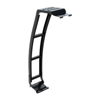
The Front Runner Ladder is designed to provide easy access to the roof of a Toyota 4Runner, facilitating the loading and unloading of gear, especially when used in conjunction with a roof rack system. It attaches securely to the vehicle's tailgate, offering a robust and stable climbing solution. The ladder's design integrates seamlessly with the vehicle's aesthetics while providing practical utility for outdoor enthusiasts and adventurers.
Important Technical Specifications
The ladder assembly comprises several key components and fasteners, ensuring a secure and durable installation.
Components:
- Ladder Top Step Bracket (Item 1): 1 unit, forms the uppermost part of the ladder, connecting to the vehicle's top hatch edge.
- Ladder Side Profile (Item 2): 2 units, the main structural elements that form the sides of the ladder.
- Bottom Mount Bracket (Item 3): 1 unit, secures the lower part of the ladder to the tailgate.
- Bottom Clamp Bracket (Item 4): 1 unit, works in conjunction with the Bottom Mount Bracket for lower attachment.
- Bottom Inner Mount PLT (Item 5): 1 unit, an internal plate for securing the bottom mount.
- Ladder Step (Item 6): 3 units, the horizontal rungs for climbing.
- U-Channel Rubber (Item 17): 1 unit (200mm long), provides protection and a snug fit where the bottom clamp bracket meets the door edge.
Fasteners and Hardware:
- Thread Forming Screw M6 x 25 (Item 7): 6 units, used for securing ladder steps and brackets.
- M6 x 16 Flange Button Head Bolt (Item 8): 6 units, for various connections within the ladder structure.
- M6 x 25 Button Head Bolt (Item 9): 3 units, for specific bracket attachments.
- M8 x 30 Button Head Bolt (Item 10): 4 units, for securing the ladder to the bottom mount bracket.
- Aluminium Spacer 10mm (Item 11): 4 units, used with M8 bolts for proper spacing.
- M6 Cage Nut (Item 12): 3 units, for internal mounting.
- M8 Nyloc Nut (Item 13): 4 units, self-locking nuts for M8 bolts.
- M6 Nyloc Nut (Item 14): 6 units, self-locking nuts for M6 bolts.
- M6 Nut Cap (Item 15): 6 units, protective caps for M6 nuts.
- M8 Nut Cap (Item 16): 4 units, protective caps for M8 nuts.
- M8 x 45 Button Head Bolt (Item 18): 1 unit, for initial clamping process.
- M8 Hex Nut (Item 19): 1 unit, for initial clamping process.
Tightening Torques:
- M6 Fasteners: 8-10 Nm (5.9 - 7.38 ft-lb).
- M8 Fasteners: 15-20 Nm (11.06 - 14.75 ft-lb).
Tools Needed:
- Torx T30
- Anti-Seize / Oil
- Anti-Rust
- Marker
- Masking Tape
- Denatured Alcohol
- Torque Wrench
- Drill with 4mm and 7mm bits
- Cordless driver (use with care)
Usage Features
The installation process is divided into several steps, emphasizing precision and safety.
Step 2.1: Initial Assembly
- Loosely assemble the Ladder Side Profiles (Item 2) to the Ladder Top Step Bracket (Item 1) using Top Mount Brackets, M6 x 16 Flange Button Head Bolts (Item 8), and M6 Nyloc Nuts (Item 14). This initial loose assembly allows for adjustments later.
Step 2.2: Securing Ladder Rungs and Bottom Mount
- Apply Anti-Seize or oil to the Thread Forming Screws (Item 7) before insertion. These screws are designed to form their own threads.
- Secure the Bottom Mount Bracket (Item 3) and Ladder Rungs (Item 6) to the Ladder Side Profiles (Item 2) using M6 x 25 Thread Forming Screws (Item 7), M6 x 16 Flange Button Head Bolts (Item 8), and M6 Nyloc Nuts (Item 14).
- Fully tighten all fasteners to 8-10 Nm. Exercise caution when using a cordless driver to avoid over-tightening.
- Place M6 Nut Caps (Item 15) over all M6 Nyloc Nuts for a finished look and protection.
Step 2.3: Marking the Tailgate
- Measure 100mm from the inside edge of the spoiler trim along the hatch edge and mark with masking tape (A). This mark guides the placement of the ladder.
Step 2.4: Preparing the Mounting Surface and Initial Placement
- Clean the surface where the Bottom Inner Mount PLT (Item 5) will be secured using denatured alcohol.
- Hook the assembled ladder from Steps 2.1 and 2.2 over the Top Mount Bracket.
- Position the ladder assembly next to the masking tape mark (A) to check alignment.
Step 2.5: Marking Bottom Position and Removing Ladder
- Ensure the ladder is level. Mark the bottom position of the ladder on the tailgate with masking tape (A).
- Remove the ladder assembly from the vehicle.
Step 2.6: Removing Rear Hatch Handle
- Open the rear hatch and remove the left-hand side handle to access the mounting area.
Step 2.7: Preparing Bottom Clamp Bracket and Drilling
- Place the U-Channel Rubber (Item 17) over the door edge where the Bottom Clamp Bracket (Item 4) will be secured.
- Align the left-hand side (A) of the Bottom Clamp Bracket (Item 4) with the masking tape applied in Step 2.5. Press the bracket against the door so the door hatch sits in the slot (B).
- Mark the hole centers (C) as shown. Drill a 4mm pilot hole and then open it up to 7mm.
- Apply Anti-Rust to the drilled holes to prevent corrosion.
Step 2.8: Assembling M6 Cage Nuts
- Assemble the M6 Cage Nuts (Item 12) to the Bottom Inner Mount PLT (Item 5).
Step 2.9: Sliding Bottom Inner Plate
- Slide the Bottom Inner Mount PLT (Item 5) into the door hatch as shown.
Step 2.10: Securing Bottom Clamp Plate
- Secure the Bottom Clamp Plate (Item 4) to the Bottom Inner Mount PLT (Item 5) using M6 x 25 Button Head Bolts (Item 9).
- Remove the backing tape from the self-adhesive tape on the Ladder Top Step Bracket (Item 1).
- Hook the ladder assembly over the top hatch edge, aligning it with the mark made earlier. Be careful not to let the adhesive tape touch the roof.
- Once aligned, angle the ladder down and firmly press the top down onto the tailgate.
Step 2.11: Final Securement
- Tip: Start with the forward LH and RH fasteners, alternating between them to pull the ladder evenly.
- Secure the ladder assembly to the Bottom Mount Bracket (Item 4).
- Initially, use the M8 x 45 Button Head Bolt (Item 18) and M8 Hex Nut (Item 19) in one of the back holes to start the clamping process.
- Then, use the M8 x 30 Button Head Bolts (Item 10), M8 Nyloc Nuts (Item 13), and Aluminium Spacers (Item 11) in the other three holes.
- Remove the M8 x 45 Button Head Bolt (Item 18) and M8 Hex Nut (Item 19) and replace them with M8 x 30 Button Head Bolts (Item 10) and M8 Nyloc Nuts (Item 13).
- Place M8 Nut Caps (Item 16) over all M8 Nyloc Nuts (Item 13).
- Tighten all M8 fasteners to 15-20 Nm (11.06 - 14.75 ft-lb).
Maintenance Features
The manual emphasizes several maintenance-related aspects to ensure the longevity and safety of the Front Runner Ladder:
- Regular Inspections: The "IMPORTANT WARNING!" section on the cover page highlights the critical need for regular inspections of all mounting points and fasteners. It states that "IMPROPER ATTACHMENT COULD RESULT IN AN AUTOMOBILE ACCIDENT, AND COULD CAUSE SERIOUS BODILY INJURY OR DEATH." Users are advised to check all fasteners and mounting points before each trip and at regular intervals (e.g., weekly, monthly, or every 1500 km/1000 miles).
- Tightening Torque: Specific tightening torques are provided for M6 (8-10 Nm) and M8 (15-20 Nm) fasteners. Adhering to these specifications is crucial to prevent loosening and ensure structural integrity.
- Anti-Seize and Anti-Rust Application: The manual explicitly instructs users to apply Anti-Seize or oil to thread-forming screws (Item 7) before insertion and Anti-Rust to drilled holes. This prevents corrosion, facilitates future disassembly, and maintains the integrity of the mounting points.
- Proper Installation: The detailed step-by-step instructions, along with warnings about using cordless drivers carefully, ensure that the initial installation is performed correctly, which is the foundation of good maintenance. The manual warns against attempting installation if unfamiliar with the procedures and recommends professional installation.
- Component Integrity: The document implies that any damaged or worn components should be replaced. While not explicitly stated as a maintenance step, the emphasis on proper assembly and regular checks suggests that maintaining the integrity of each part is essential.
- Online Fitment Guide: The manual directs users to "CHECK ONLINE FOR THE LATEST FITMENT GUIDE" at www.frontrunneroutfitters.com, indicating that updated information or specific maintenance tips might be available there.
By following these guidelines, users can ensure the Front Runner Ladder remains safe, secure, and functional for its intended purpose, contributing to a reliable and enjoyable outdoor experience.