*NOTE- When attaching heavy scraper kit, do
NOT tighten any hardware until stated in direc-
tions. Adjustments may need to be made.
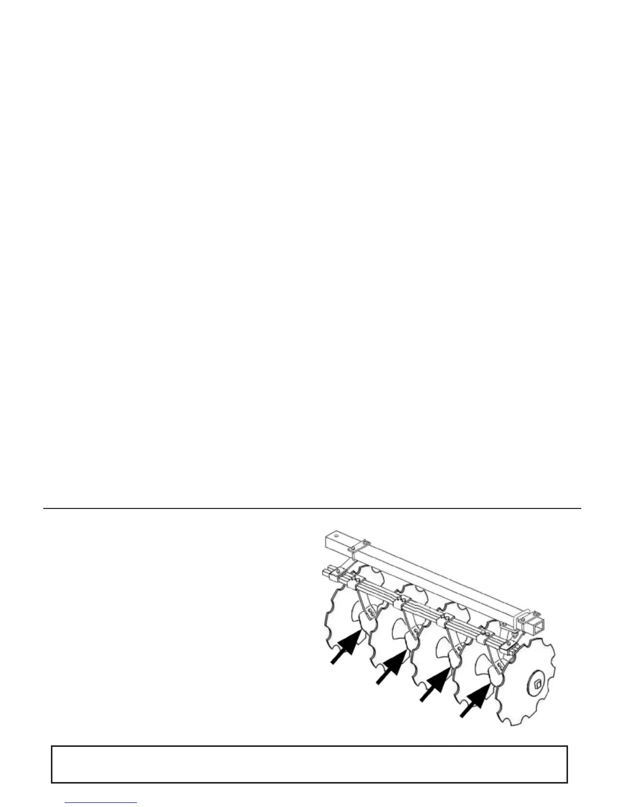
Reference Figure 4
To attach heavy scraper kit to disc, place scraper
bar top plate (Figure 4, ref. #2) on top of gang
beam and scraper mount bracket (ref. #1) on bot-
tom of gang beam. Using 5/8" x 5" Gr. 2 bolts
(ref. #3), fasten both pieces together around
gang beam with 5/8" lock washer and hex nut
(ref. #4 & #5). There should be two scraper
mount bracket assemblies for each gang beam
with the placement being close to each gang
hanger. Some adjustment may need to be made
when mounting scraper arm & blade assemblies
(ref. #16). Take heavy scraper bar (ref. #13) and
mount on top of scraper mount bracket assembly
with 1-hole scraper bar clamp (ref. #11). Use a
1/2" x 2 1/2" Gr. 2 bolt (ref. #6) and a 1/2" flange
locknut (ref. #7) to fasten. Scraper arm & blade
assemblies (ref. #16) are now mounted on bot-
tom of scraper bar (ref. #13). There are two dif-
ferent sides of scraper arm & blade assemblies
(ref. #16). One side fits the right front and left
rear, the other side fits the left front and right rear.
When mounting scraper arm & blade assemblies
(ref. #16) to bottom of scraper bar (ref. #13), use
2-hole clamp (ref. #12) on top of scraper bar (ref.
#13) and fasten together with 1/2" x2 1/2 GR 2
bolt(ref. 6) and 1/2” flange locknut (ref. #7).
Scraper arm & blade assemblies are not provided
for outside front and inside rear blades! Once all
scraper arm & blade assemblies (ref. #16) have
been mounted, now is the time to make adjust-
ments to scraper mount bracket assemblies, if
needed. When adjustments are made, tighten
scraper mount bracket assemblies to gang beam
and tighten scraper bar (ref. #13) to scraper
mount bracket assembly using 1-hole scraper
bar clamp (ref. #11) and hardware (ref. #6 & #7).
Scraper arm & blade assemblies (ref. #16) should
then be positioned as close to the disc blade as
possible without touching it. Turning the gang
after mounting each scraper arm & blade assem-
bly (ref. #16) will help determine the correct
mounting position of each one. This is recom-
mended to prevent dragging or binding of the
gang.
*NOTE- Tighten all fasteners after setting and
adjustments are made. Please see Bolt and
torque Chart on page 19.
*NOTE- Re-tighten all fasteners after first opera-
tional use. Please see Bolt and Torque Chart on
page 19.
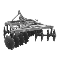
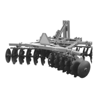
Heavy Scraper Kit Mounting Instructions
Optional Equipment 18
Regardless of model or conguration, scrapers
are only located between two disk blades(Refer
to the diagram to the right). There is no need for
a scraper on the far right blade on the front gangs
or the far left blade on the rear gangs.