Pre-Assembly
The DH34 is shipped from the factory unassem-
bled. The numbers referenced below are from the
DH34 parts catalog, Figure 3 on page 14. When
assembly is complete tighten all bolts according to
the torque and bolt chart on page 19.
Remove the bag from the pallet which contains the
u-bolts and hardware. Cut the bands(Photo 1) from
the pressure control assembly (ref. #16,17,18,19)
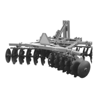
and the mast and pivot weldment (ref. #6). Attach
(Photo 2) the spring end of the pressure control
assembly (ref. # 16,17,18,19) to the main frame
using the rear pivot pin (ref. #43) which is already
in main frame. Once this is attached, rotate the
mast and pivot weldment (ref. #6) upwards. Using
the front pivot pin (ref. #41), which is already in the
mast and pivot weldment (ref. #6), connect the two.
When finished, cut all bands from the pallet and
remove all remaining components.
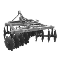
Using a hoist(Photo 3), raise frame approximately
28” off the ground. Loosen the gang beam clamps
(ref. #11 & #12) and the gang beam pivot clamps
(ref. #9) on front and rear of unit. *DO NOT
REMOVE* these were pre-assembled on the unit
at the factory. Slide gang beam (ref. #8) through
gang beam clamp (ref. #11 & #12) and gang beam
pivot clamp on front of unit. Repeat the same pro-
cess on the rear gang beam (ref. #8).
To attach gangs, reference the gang assembly
chart on page 10. Find the model purchased and
attach the gangs to the main frame using the
u-bolts (ref. #20) and hardware (ref. #22 & 23) from
the bag removed earlier. Position the gangs under
the frame using the diagram and measurements
given on page 9. Each model has one gang with an
outrigger washer attached (ref. # 37). This gang is
to be placed on the right rear of the unit with the
washer facing out. Once gangs have been posi-
tioned and attached to gang beam (ref. # 8), the
gang beam will then need to be laterally positioned
on the frame. See measurements on page 10.
When this is finished, tighten the gang beam
clamps (ref. #11 & #12) and the gang beam pivot
clamps (ref. #9).
The SMV sign (ref. #10) should be bolted on with
the hardware provided on the back side of the
frame (see Figure 3, page 14)
9 Dealer Instructions
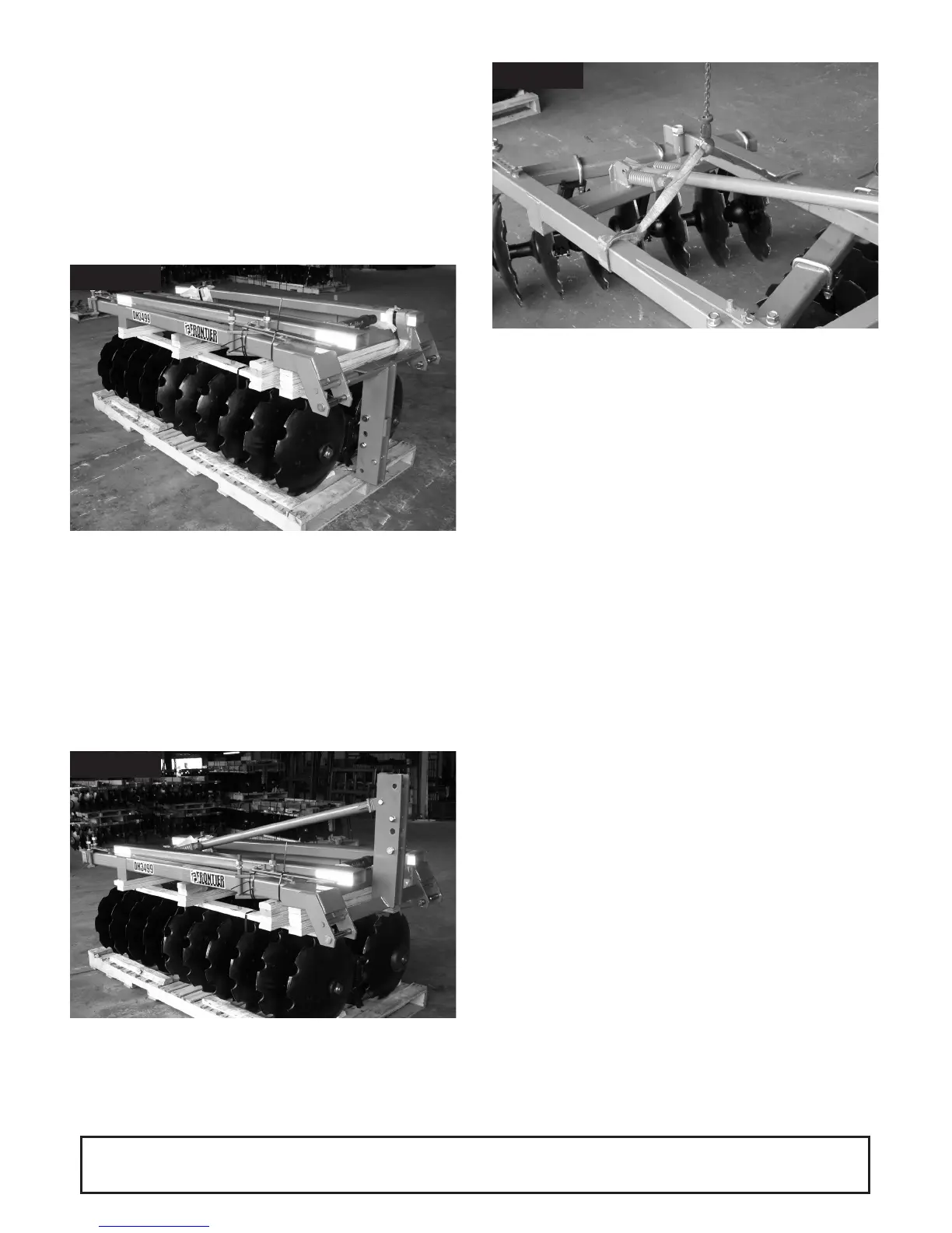
Photo 1
Photo 3
Photo 2