b. If you don’t already have holes in the correct location, mark where the screws need to go with a pencil using the
screw holes on the back plate as a guide. Use a ¼” drill bit to drill new holes into the marked spots. Tap the drywall
anchors into the holes, and then screw in your screws, ensuring you have fed the wires through the center hole of
the back plate first.
Note: Installing the drywall anchors are for extra support, but are not required for a successful installation.
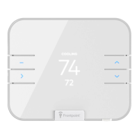
10. Check that the wires have exposed ends of at least 1/4”, as indicated in the image below. If not, you can peel back the color
coating with your fingers.
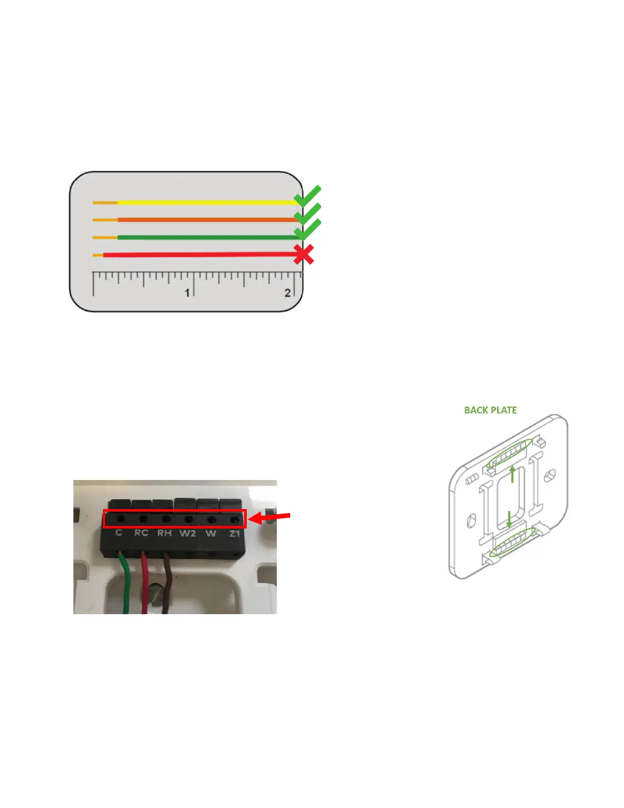
11. Match each wire to the corresponding terminal tab. Insert each of the wires into the corresponding hole, parallel to the
wall (going upwards and downwards, as indicated with arrows in the line art below).
When the wire has been sufficiently inserted, the corresponding terminal tab will become indented. “Terminal tabs” are
circled in the line art for further clarity.
Tip: Although your wire configuration may be different, please refer to the below
photo to understand that the set of holes you should utilize are alongside the
edge of the terminal blocks. The holes on top are where the pins of the
thermostat will be inserted.
* If you see an R wire, connect it to RH.
**If there are both RC and RH wires, it is critical that each wire is inserted into its corresponding hole and the subsequent
configuration is done correctly. In this scenario, Frontpoint highly recommends calling an HVAC professional to help with
the installation.
***Z1 or Z2 can be used for W3, H, DH, or EX.
 Loading...