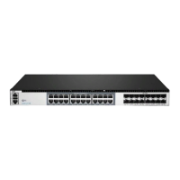
The IES3100-8T4F-P is an L2+ Managed Industrial Switch designed for robust network deployments in commercial and industrial environments. This quick start guide provides an overview of the switch's hardware, installation requirements, and basic configuration steps.
Function Description:
The IES3100-8T4F-P is a managed industrial switch that offers L2+ features, enabling advanced network management and control. It is designed to provide reliable Ethernet connectivity in demanding industrial settings. The switch supports both copper (RJ45) and fiber (SFP) connections, offering flexibility for various network architectures. Its managed capabilities allow for detailed configuration, monitoring, and troubleshooting, ensuring optimal network performance and security. The device also supports Power over Ethernet (PoE+), allowing it to power compatible terminal devices directly through the Ethernet cable, simplifying deployments and reducing cabling requirements.
Important Technical Specifications:
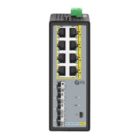
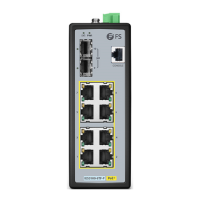
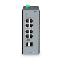
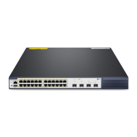
Front Panel Ports:
- RJ45 Ports: 10/100/1000BASE-T ports for Ethernet connection. These ports support standard Ethernet cables (UTP) with RJ45 connectors.
- SFP Ports: SFP ports for 1G fiber optic connections. These ports require compatible SFP transceivers and fiber optic cables.
- CLI Port: An RJ45 console port for serial management, used for initial configuration and advanced troubleshooting.
Front Panel LEDs:
- PWR LED:
- On: Power is being supplied to power input.
- Off: Power is not being supplied to power input.
- SYS LED:
- Blinking: The system is ready for operation.
- Off: No supply voltage or the system is not ready for operation.
- RJ45 LEDs (Link/Act & PoE):
- Yellow (PoE):
- On: A PoE terminal device is connected and receiving power via PoE.
- Off: No PoE port is available or power over Ethernet function is disabled.
- Green (Link/Act):
- On: The port is linked.
- Blinking: The port is transmitting data.
- Off: The port is not linked.
- SFP LEDs:
- On: The port is linked.
- Blinking: The port is transmitting data.
- Off: The port is not linked.
Upper Panel:
- Grounding Point: Used for connecting the grounding cable to a proper earth ground, ensuring electrical safety.
- Terminal Block Connector: Consists of 5 contacts for DC power input.
- Pin 1 (+): Positive DC power input for PWR1.
- Pin 2 (-): Negative DC power input for PWR1.
- Pin 3 (Ground): Requires a good ground connection.
- Pin 4 (+): Positive DC power input for PWR2 (for redundant power).
- Pin 5 (-): Negative DC power input for PWR2 (for redundant power).
- The wire gauge for the terminal block should be in the range from 12 to 16 AWG.
Back Panel:
- DIN Rail Mounting Clip: Used for mounting the switch on a DIN rail.
- Single DC (48-57VDC) Input: Connect positive/negative DC power wires into Contacts 1 and 2 for PWR1.
- Dual Redundant DC (48-57VDC) Input: Connect positive/negative DC power wires into Contacts 1 and 2 for PWR1 and Contacts 5 and 4 for PWR2.
Usage Features:
Mounting the Switch:
- DIN-Rail Mounting:
- Grip the top of the DIN rail mounting clip onto the edge of the DIN rail.
- Press the bottom of the clip onto the other side of the DIN rail.
- Push the bottom of the clip outwards to remove it easily.
- Grounding the Switch:
- Connect one end of the grounding cable to a proper earth ground.
- Secure the grounding lug to the grounding point on the switch's upper panel with a screw and washers.
- Caution: The earth connection must not be removed unless all supply connections have been disconnected.
Connecting Ports:
- Connecting RJ45 Ports:
- Connect an Ethernet cable to the RJ45 port of a camera, outdoor AP, computer, or another network device.
- Connect the other end of the Ethernet cable to the RJ45 port of the switch.
- Connecting SFP Ports:
- Remove the dust plugs from the SFP ports.
- Plug the compatible SFP transceiver into the SFP port.
- Connect a fiber optic cable to the fiber transceiver, and then connect the other end of the cable to another fiber device.
- Connecting the Console (CLI) Port:
- Insert the RJ45 connector into the RJ45 console port on the front of the switch.
- Connect the DB9 female connector of the console cable to the serial port on the computer.
Connecting the Power:
- The switch's upper panel has a DC inlet power socket with a 5-contact terminal block connector.
- For Single DC (48-57VDC) Input: Insert positive/negative DC power wires into Contacts 1 and 2 for PWR1 and tighten the wire-clamp screws.
- For Dual Redundant DC (48-57VDC) Input: Insert positive/negative DC power wires into Contacts 1 and 2 for PWR1 and Contacts 5 and 4 for PWR2, then tighten the wire-clamp screws.
Configuring the Switch:
- Using the Console Port (CLI):
- Connect a computer to the console port of the switch using the console cable.
- Start terminal simulation software (e.g., HyperTerminal).
- Set HyperTerminal parameters: Baud rate to 115200, Data bits to 8, Parity to None, Stop bits to 1.
- Click "Connect" to enter the CLI.
- Using the Web-Based Interface:
- Connect a computer to the management port of the switch using a network cable.
- Set the computer's IP address to 192.168.1.x (where "x" is any number from 2 to 254).
- Open a web browser, type
http://192.168.1.1, and enter the default username/password (admin/admin).
- Click "Login" to access the web-based configuration page.
- Note: It is recommended to use Internet Explorer 8.0 or above. If the web interface is inaccessible, temporarily disable anti-virus software or firewall.
Maintenance Features:
Troubleshooting:
- 100M/1G Port Is Not Working:
- Ensure the optical module and cable are functioning correctly.
- Check if the configuration at both ends of the communication device is set to auto or forced rate.
- Connecting the Switch Remotely Unsuccessfully:
- Test network connectivity using ping.
- If the network is reachable, try restarting the switch.
- Check if the corresponding service is enabled.
- The Port Is Not Working, the LED Indicator Is Off:
- Ensure the switch ports are in the "no shutdown" state.
- Check if the switch can read the DDM (Digital Diagnostic Monitoring) information.
- Verify that the port speed setting is correct.
- Try looping the switch cable.
- RJ45 Port Is Not in Connectivity or It Is Erroneous in Receiving/Transmitting Frames:
- Replace the twisted pair cable.
- Check if the port configuration has the common working mode with the connected switch.
Product Warranty:
- FS offers a 5-year limited warranty against defects in materials or workmanship for the IES3100-8T4F-P switch.
- Free returns are available within 30 days for damaged or faulty items due to workmanship (excluding custom-made items or tailored solutions).
- Information on warranty and return procedures can be found on the FS website.
- FCC: The device complies with part 15 of the FCC Rules for Class A digital devices, designed to provide reasonable protection against harmful interference in a commercial environment. It must accept any interference received and not cause harmful interference.
- CE: FS.COM GmbH declares that this device complies with Directive 2014/30/EU and 2014/35/EU. The EU Declaration of Conformity is available on the FS website.
- UKCA: FS.COM Innovation Ltd declares that this device complies with Directive SI 2016 No. 1091 and SI 2016 No. 1101.
- IC (Innovation, Science and Economic Development Canada): The device contains license-exempt transmitter(s)/receiver(s) that comply with RSS(s). Operation is subject to not causing interference and accepting any interference. It complies with CAN ICES-003(A)/NMB-003(A) and meets the exemption from routine evaluation limits in section 2.5 of RSS 102 for RF exposure. The equipment should be installed and operated with a minimum distance of 30cm between the radiator and the user's body.