Do you have a question about the FS S3410 Series and is the answer not in the manual?
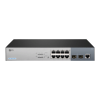
Details the various ports on the front panel of the S3410-10TF-P model for connectivity.
Illustrates and describes the back panel components and connections of the switches.
Shows the location and types of LEDs on the front panel of the S3410-10TF-P for status.
Details the function of the PoE and RESET buttons located on the front panel.
Specifies the environmental conditions, such as temperature and dust, for proper switch installation.
Instructions for placing the switch on a desk using rubber pads for stability.
Steps to secure mounting brackets to the switch for installation in a standard equipment rack.
Procedure for mounting the switch on a wall using provided mounting brackets and screws.
Steps to configure the switch via its web-based interface, including IP settings.
Instructions for configuring the switch using the console port and terminal simulation software.
Troubleshooting steps for console output issues and illegible characters.
Guidance for resolving issues with 1/10G ports not functioning correctly.
Steps to troubleshoot unsuccessful remote switch connections.
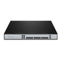
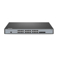
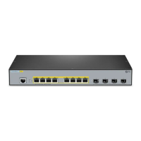
The FS S3410 Series Managed L2+ Gigabit PoE+ Switches are designed to provide robust and reliable network connectivity, offering a range of features for efficient network management and power delivery. These switches are available in several models: S3410-10TF-P, S3410-24TS-P, and S3410-48TS-P, each tailored to different port density requirements.
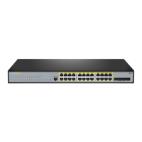
The primary function of these switches is to provide managed Layer 2+ switching capabilities with Gigabit Ethernet speeds and Power over Ethernet Plus (PoE+) support. This means they can not only forward data traffic at high speeds but also supply power to connected devices such as IP cameras, IP telephones, and wireless access points (APs) directly through the Ethernet cable. The "L2+" designation indicates advanced Layer 2 features, often including some basic Layer 3 routing capabilities, which allows for more sophisticated network segmentation and traffic management than a standard Layer 2 switch.
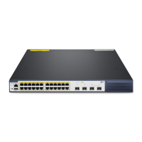
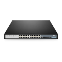
The S3410-10TF-P model features 10/100/1000BASE-T RJ45 ports for Ethernet connections and SFP ports for 1G fiber connections. It also includes an RJ45 console port for serial management, allowing for command-line interface (CLI) configuration. The S3410-24TS-P and S3410-48TS-P models offer higher port densities, with 24 and 48 10/100/1000BASE-T RJ45 ports respectively. These models also include RJ45/SFP combo ports, where either an RJ45 or an SFP slot can be active at a time, providing flexibility for copper or fiber connections. Additionally, they feature SFP+ ports for 1/10G connections, enabling high-speed uplinks or stacking. A USB port is reserved on these models, indicating potential for future functionality or configuration backup.
The PoE+ capability adheres to the IEEE 802.3at standard, allowing for more power per port compared to standard PoE, which is crucial for power-hungry devices. The switches are designed to be managed, meaning they offer a web-based interface and a console port for detailed configuration and monitoring of network parameters, VLANs, QoS, security features, and PoE settings.
The S3410 series switches are designed for flexible deployment in various network environments. They support multiple mounting options, including desk mounting, rack mounting, and wall mounting, making them suitable for different physical setups.
For desk mounting, rubber pads are provided to ensure stability and prevent scratching surfaces. Rack mounting is facilitated by mounting brackets and M4 screws, allowing the switch to be securely installed in a standard 19-inch rack. Wall mounting also uses mounting brackets and expansion screws, specifically designed for concrete or other non-combustible surfaces.
Connecting the switch involves straightforward procedures. Power connection is made via an AC power cord to the power port on the back of the switch. For models with dual power supplies, this setup provides redundancy, enhancing reliability. Grounding the switch is a critical safety step, involving connecting a grounding cable to a proper earth ground, such as the rack, and securing it to the grounding point on the switch's back panel.
Network devices like IP cameras, IP telephones, and access points can be connected to the RJ45 ports using standard Ethernet cables. For fiber optic connections, compatible SFP/SFP+ transceivers are plugged into the respective ports, and fiber optic cables are then connected to these transceivers. Users are cautioned about laser beams from optical modules and fibers, emphasizing the need for eye protection.
Serial management is performed through the RJ45 console port. A console cable connects the switch to a computer's serial port, allowing for CLI access using terminal simulation software. This method is often preferred for initial setup or advanced troubleshooting.
A significant feature for the S3410-24TS-P and S3410-48TS-P models is their stacking capability. Up to four switches of the same series can be physically stacked together using optical fiber cables connected to SFP+ transceivers or 10G Direct Attach Cables (DAC). This allows for increased port density and simplified management of multiple switches as a single logical unit. The S3410-10TF-P model, however, is not stackable.
The switches provide visual feedback through various front panel LEDs, indicating the status of power, system operation, PoE, and individual RJ45 and SFP/SFP+ ports. These LEDs help users quickly assess the operational status and diagnose potential issues. For instance, a solid green STATUS LED indicates the switch is operational, while blinking green suggests system initialization or errors. PoE LEDs indicate the PoE state, and RJ45/SFP/SFP+ LEDs show connection status, speed, and traffic activity.
Configuration and management can be done via a web-based interface or the console port. The web interface offers a graphical user interface (GUI) for easier configuration, accessible by connecting a computer to an Ethernet port of the switch, setting a specific IP address, and then navigating to the switch's default IP address in a web browser. The console port provides a command-line interface (CLI) for more granular control and scripting.
The S3410 series switches are designed with maintenance in mind, offering features that simplify troubleshooting and ensure continuous operation.
The LED indicators on the front panel are a primary tool for quick status checks and initial troubleshooting. Different colors and blinking patterns provide immediate information about the switch's overall health, power supply status, expansion module status, and individual port connectivity and activity. For example, a solid yellow STATUS LED indicates a temperature warning, prompting an immediate check of the working environment. A solid red STATUS LED signifies a faulty switch, indicating a more serious issue.
For models with modular power supplies (S3410-24TS-P and S3410-48TS-P), the ability to install and remove power supply modules allows for easy replacement in case of failure, contributing to higher availability. The PWR1/PWR2 LEDs indicate the status of these power modules, with solid green signifying operational power supply and solid red indicating an abnormal power cord or switch issue.
The switches come with dust plugs for idle optical ports. Users are advised to keep these dust plugs properly and use them to protect unused SFP/SFP+ ports from dust and contamination, which can degrade optical performance and lead to connection issues.
Troubleshooting guidance is provided for common issues. If a serial port console has no output or illegible characters, users are advised to check the serial port connection and ensure the parameter configuration (baud rate, data bits, parity, stop bits, flow control) matches the specified settings. For 1/10G ports that are not working, even with compatible cables and transceivers, modifying the port mode or forcing the port speed is suggested. If a port is not working and its LED indicator is off, users should verify that the port is not in a "no shutdown" state, check DDM information, confirm correct port speed settings, and try looping the switch cable. For RJ45 ports experiencing connectivity issues or erroneous frame reception/transmission, replacing the twisted pair cable and ensuring common working mode configuration with the connected switch are recommended steps.
The RESET button on the S3410-10TF-P model provides a way to restart the switch. Pressing and holding it for more than five seconds initiates a restart after ten seconds, which can be useful for resolving certain operational issues.
The managed nature of these switches means that detailed logs and diagnostic tools are typically available through the web interface or CLI, allowing network administrators to monitor performance, identify errors, and troubleshoot complex network problems.
FS provides comprehensive support resources, including a download center for documentation and firmware, a help center for general assistance, and direct contact options for customer support. The products are backed by a 5-year limited warranty against defects in materials or workmanship, with clear policies for returns, ensuring long-term reliability and customer confidence.
| Series | S3410 |
|---|---|
| Layer | Layer 2+ |
| Managed | Yes |
| Model | S3410 Series |
| Type | Switch |
| Ports | 10/100/1000BASE-T |
| Uplink Ports | 4 x 10G SFP+ |
| Switching Capacity | 128 Gbps |
| Forwarding Rate | 95.2 Mpps |
| MAC Address Table | 16K |
| Jumbo Frame | 9K |
| Power Supply | AC |
| Dimensions (W x D x H) | Varies by model |
| Dimensions | 440 x 260 x 44 mm |
| Operating Temperature | 0°C to 45°C |
| Storage Temperature | -40°C to 70°C |
| Operating Humidity | 10% to 90% non-condensing |
| Storage Humidity | 5% to 95% non-condensing |
| Management | CLI, SNMP |
| PoE | Yes (selected models) |