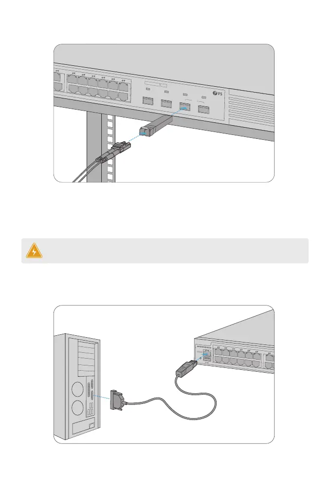
Connecting the Console Port
PoE
STATUS
M1
M2
PWR1
PWR2
PoE
1
2
3
4
5
6
7
8
9
10
11
12
13
14
15
16
17
18
19
20
21
22
23
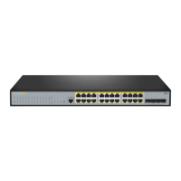
Green=1000M Yellow=10/100M On=Link Flashing=ACT PoE LED:Green=Good Supply Yellow=Over Load
CONSOLE
1. Plug the compatible SFP/SFP+ transceiver into the SFP/SFP+ port.
2. Connect a ber optic cable to the ber transceiver. Then connect the other end of the cable to
another ber device.
WARNING: Laser beams will cause eye damage. Do not look into bores of optical modules
or optical bers without eye protection.
Connecting the SFP/SFP+ Ports
1. Insert the RJ45 connector into the RJ45 console port on the front of the switch.
2. Connect the DB9 female connector of the console cable to the serial port on the computer.
PoE
1
2
3
4
5
6
7
8
9
10
11
12
13
14
15
16
17
18
19
20
21
22
23
24
24
25
26
23
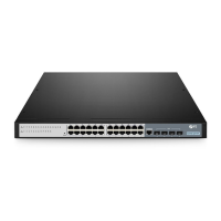
Green=1000M Yellow=10/100M On=Link Flashing=ACT PoE LED:Green=Good Supply Yellow=Over Load
SFP+
S3410-24TS-P
PoE+
 Loading...