Connecting the RJ45 Ports
1. Connect an Ethernet cable to the RJ45 port of IP cameras, IP telephone, Access Points (AP), or other
network devices.
2. Connect the other end of the Ethernet cable to the RJ45 port of the switch.
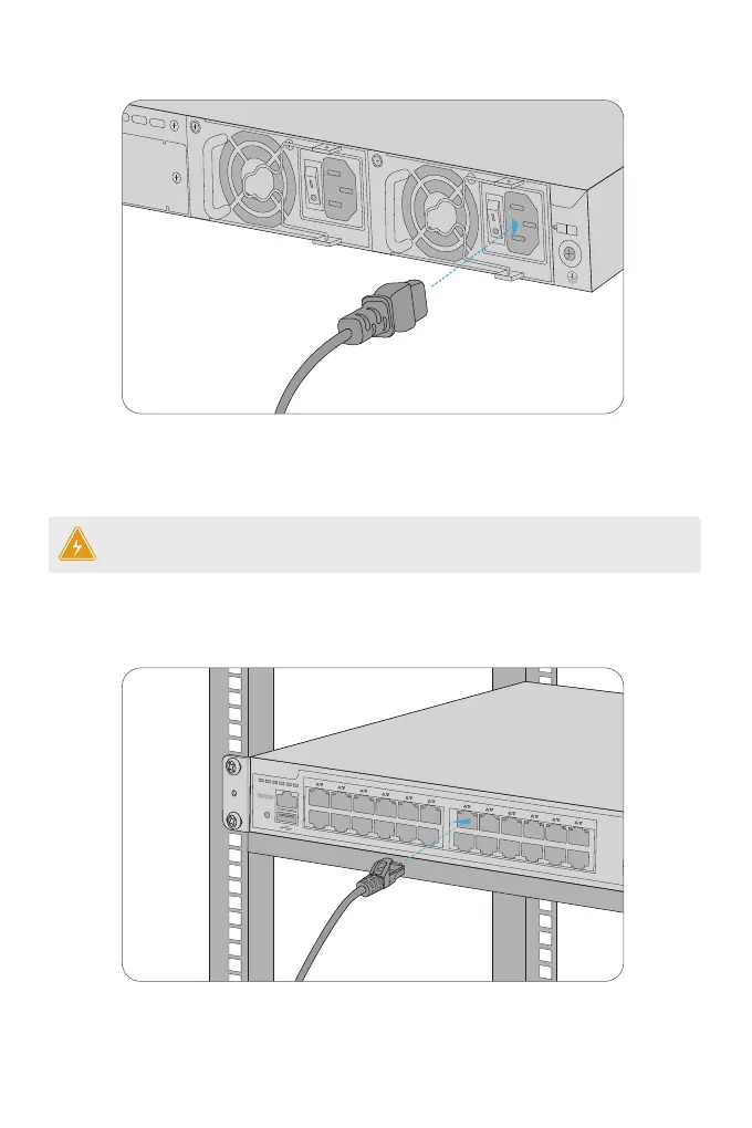
Connecting the Power
1
Power
2
Input
Module2
Output
Input
Output
PoE
STATUS
M1 M2
PWR1
PWR2
PoE
1
2
3
4
5
6
7
8
9
10
11
12
13
14
15
16
17
18
19
20
21
22
23
24
24
25
23
Green=1000M Yellow=10/100M On=Link Flashing=ACT PoE LED:Green=Good Supply Yellow=Over Load
CONSOLE
SFP+
S3410-24TS-P
PoE+
1. Plug the AC power cord into the power port on the back of the switch.
2. Connect the other end of the power cord to an AC power source.
WARNING: Do not install power cable while the power is on.
 Loading...