EN
7
Pin 1 / 5
Positive (+) Pin Negative (-) Pin
Pin 2 / 4
2. Insert positive/negative AC/DC power wires into Contacts + and - for Power 1 and Power 2, then
release the button.
1
V1- V1+
PWR1 PWR2
V2+ V2-
2 3 4 5
CONSOLE
PWR1
PWR2
SYS
100-240V
PWR
PWR1/PWR2
5 9
13
17 21 25
6
10
14 18 22 26
7
11
15 19 23 27
8
12
16 20 24 28
1
2
3
4
65
87
109
14
13
16
15
18
17
20
19
2221
2423
N L
IES5100-24TF
2625
2827
AC
DC
L N
2
1
4 3
12
11
SFP
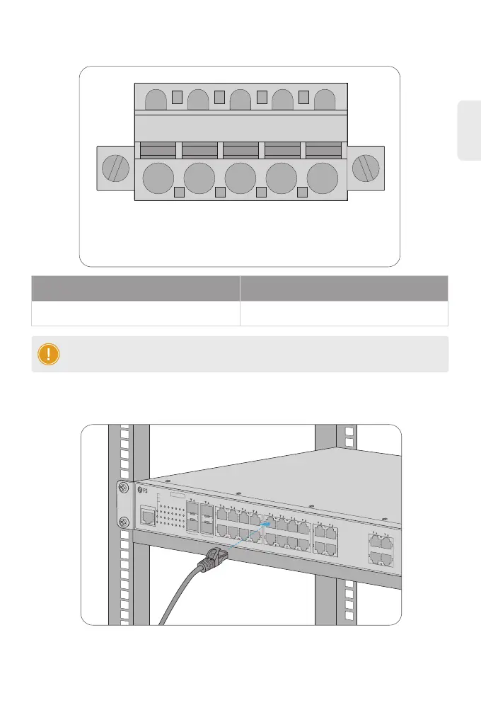
Connecting the RJ45 Ports
1. Connect an Ethernet cable to the RJ45 port of a computer, printer, network storage, or other
network devices.
2. Connect the other end of the Ethernet cable to the RJ45 port of the switch.
NOTE: The wire gauge for the terminal block should be in the range of 12-24 AWG.
 Loading...